


Vertiv™ NetSure™ 512
NGBB
-48 VDC Power System User Manual
Proprietary and Confidential © 2022 Vertiv Group Corp.
5
2.4
Local Controls and Indicators
2.4.1
General
Refer to the Controller, Rectifier, and Converter Instructions for descriptions of the local controls and indicators located on these units.
Refer to the next section for descriptions of the local controls and indicators located on the circuit cards installed inside the List 27
distribution cabinet.
2.4.2
List 27 Distribution Cabinet Local Controls and Indicators
Optional Manual Battery Disconnect Circuit Card
The optional manual battery disconnect circuit card contains a manual battery disconnect switch and indicator. Refer to
Optional Critical Alarm Indicator
The system may be equipped with an optional critical alarm indicator which illuminates if the controller issues a critical alarm. Refer to
Figure 2.2.
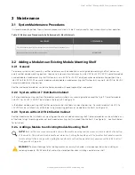
Figure 2.1 Optional Manual Battery Disconnect Circuit Card - List 27 Distribution Cabinet
Momentary UP / Middle / Momentary Down
Momentary UP Position:
Closes (latches in close position) the Battery Disconnect Contactor.
Middle Position:
Normal Operation.
Momentary DOWN Position: Opens (latches in open position) the Battery Disconnect Contactor.
Momentarily place switch in the UP position to close the contactor.
Manual Battery Disconnect Active Indicator
Manual Battery
Disconnect Switch
Illuminates if the Battery Disconnect Contactor has
been manually disconnected (placed in open position).


