Vertiv™ NetSure™ 512
NGBB
-48 VDC Power System User Manual
Proprietary and Confidential © 2022 Vertiv Group Corp.
14
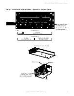
Figure 3.7
Installing a Field Expansion Module Mounting Shelf in a System with List 27 Distribution Cabinet - Controller CAN
Bus
Exploded View Shown to
Illustrate Wire Connections Only
to Controller
to Termination
Plug
Existing Module
Mounting Shelf
Existing Module
Mounting Shelf
These connectors
are factory connected.
These connectors
are factory connected.
These connectors
are factory connected.
Existing Module
Mounting Shelf
Expansion Module
Mounting Shelf
Disconnect cable coming
from distribution cabinet
from this connector on
bottom-most existing
shelf, then connect to the
same connector on the
expansion shelf.
Now connect these
two connectors togethe r.
Rear View
Factory provided jumper
to bring connectors to
same side of shelf.
Rear View
Factory provided jumper
to bring connectors to
same side of shelf.
Rear View
Factory provided jumper
to bring connectors to
same side of shelf.
Rear View
Factory provided jumper
to bring connectors to
same side of shelf.
X


