4-6
39014-03 06/16
VERSALIFT VST-36/40/47/52-I
OPERA
TION
control lever and indicates which direction to move
the control lever for the desired movement. When
released the control lever will return to the centered or
neutral position and motion ceases.
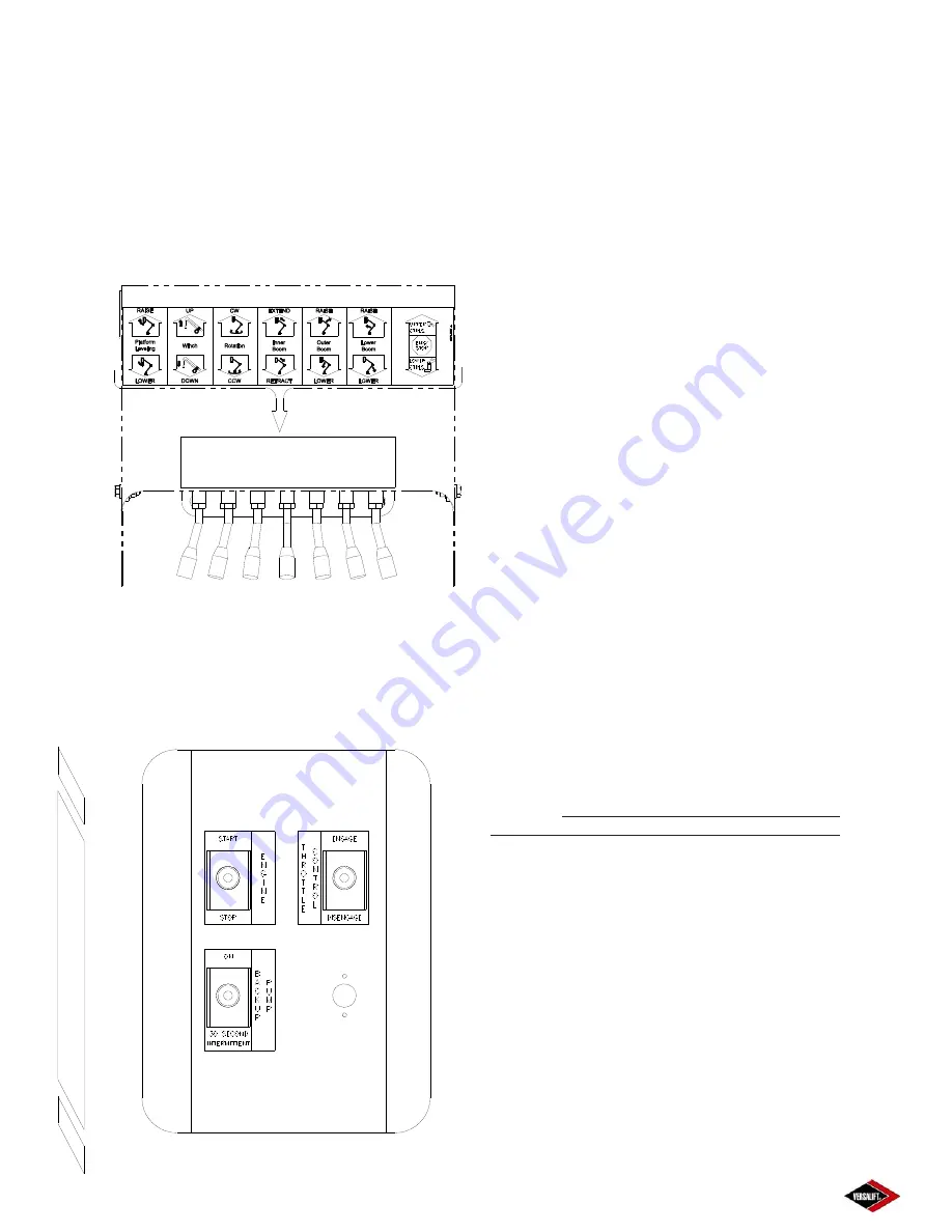
PLATFORM LEVELING CONTROL
- This control
activates the hydraulic platform leveling to level the
platform.
Lower Controls at Turret
Figure 4.4
ELECTRIC SELECTOR STATION
- The electric
controls at the pedestal are arranged as shown in
Figure 4.5 A description of each control and the
method of operation is given below.
Electric Control Station at the Pedestal
Figure 4.5
ENGINE START/STOP CONTROL (Standard)
- The
engine start/stop control is convenient for the ground
crew at the pedestal. The engine start/stop control is
operated by a three-position toggle switch.
To start the engine from the pedestal
, push the
toggle to the “START/STOP” position and hold the
toggle in that position for a moment until the engine
starts. Allow the toggle to return to the neutral or
centered position.
To stop the engine from the pedestal
, push the
toggle to “START/STOP” again. Allow the toggle to
return to the neutral or centered position. Refer to
Section 5, “Emergency Operation” for information on
the use of this control in an emergency.
TWO-SPEED MANUAL THROTTLE CONTROL
(Option)
- Gives the operator a choice of efficient,
economical engine idle speed or higher engine speed
when faster lift movements are required. The two-
speed throttle control will operate only if the master
control is activated. The two-speed throttle control
is operated by a three-position toggle switch at the
pedestal.
To speed up the engine from the pedestal
, push
the toggle to the “ENGAGE” position. Allow the toggle
to return to the neutral or centered position.
To slow the engine to an idle from the pedestal
,
push the toggle to the “DISENGAGE” position. Allow
the toggle to return to the centered or neutral position.
BACKUP PUMP CONTROL (Option)
- If the aerial
lift main power source fails, the backup pump option
can be activated to operate the lift. The backup pump
control is a detented toggle switch located at the
pedestal. The backup pump system should not be
operated longer than 30 seconds continuously.
Continuous use will drain the battery and damage (over
heat) the backup pump motor.
To activate the backup pump from the pedestal
,
push the toggle switch to the “ON” position and operate
the appropriate lift controls.
To deactivate the backup pump from the
pedestal
, push the toggle switch down (towards the
“30 SECOND INTERMITTENT” message).
REMOTE CONTROLS (Optional)
- The hand-held
remote control and remote lower control box are shown
in Figure 4.6 and 4.7. The remote lower controls
consist of a series of spring loaded toggle switches
and a control selector switch. Moving the control
switch in the direction of the arrow, with the control
selector in the “lower” position, causes the aerial lift
Summary of Contents for VST-36-I
Page 2: ......
Page 4: ......
Page 6: ......
Page 11: ...2 3 39014 03 06 16 VERSALIFT VST 36 40 47 52 I RESPONSIBILITIES SAFETY ...
Page 12: ...2 4 RESPONSIBILITIES SAFETY 39014 03 06 16 VERSALIFT VST 36 40 47 52 I ...
Page 18: ......
Page 27: ...3 9 39014 03 06 16 VERSALIFT VST 36 40 47 52 I SPECIFICATIONS ...
Page 28: ...3 10 39014 03 06 16 VERSALIFT VST 36 40 47 52 I SPECIFICATIONS ...
Page 29: ...3 11 39014 03 06 16 VERSALIFT VST 36 40 47 52 I SPECIFICATIONS ...
Page 30: ...3 12 39014 03 06 16 VERSALIFT VST 36 40 47 52 I SPECIFICATIONS ...
Page 31: ...3 13 39014 03 06 16 VERSALIFT VST 36 40 47 52 I SPECIFICATIONS ...
Page 36: ...3 18 39014 03 06 16 VERSALIFT VST 36 40 47 52 I SPECIFICATIONS ...
Page 37: ...3 19 39014 03 06 16 VERSALIFT VST 36 40 47 52 I SPECIFICATIONS ...
Page 38: ......
Page 60: ...6 4 39014 03 06 16 VERSALIFT VST 36 40 47 52 I DAILY VISUAL INSPECTION ...
Page 61: ...6 5 39014 03 06 16 VERSALIFT VST 36 40 47 52 I DAILY VISUAL INSPECTION ...
Page 62: ...6 6 39014 03 06 16 VERSALIFT VST 36 40 47 52 I DAILY VISUAL INSPECTION ...


