


4-13
39014-03 06/16
VERSALIFT VST-36/40/47/52-I
OPERA
TION
DANGER:
EXCEEDING THE
MAXIMUM LIFTING CAPACITY OF THE LIFT OR
THE JIB MAY CAUSE EQUIPMENT FAILURE
RESULTING IN DEATH OR SERIOUS INJURY.
Jib Capacity Component Description - The inner
boom is color coded. A green stripe aligns with the
end of the outer boom to indicate when the inner
boom is fully retracted. The inner boom is painted
white from 0 to 36 inches of extension. After 36
inches, the exterior of the inner boom is painted red.
The inner boom is equipped with a pointer and jib
capacity decal. The pointer responds to gravity, so
as the boom angle changes, the pointer tracks to
different areas of the decal. The decal is divided in
to three zones - one green, one white, and one red.
The jib pole is equipped with a maximum capacity
decal near the pivot.
Procedure to Determine the Jib Capacity:
1.
Determine the color of the inner boom where it
exits the outer boom. It will be green, white, or
red.
2.
Read the capacity from the inner boom pointer.
If the boom in step 1 was green, read the capacity
from the green portion of the decal. If the boom in
step 1 was white, read the capacity from the white
portion of the decal. If the boom in step 1 was
red, read the capacity from the red portion of the
decal.
3.
Check the capacity of the jib pole by reading the
decal near the jib pole tilt pivot.
4.
The actual lifting capacity is the smaller of the
two capacities determined in steps 2 and 3.
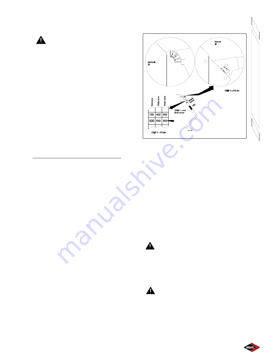
Example – See Figure 4.12
1.
In this example, the inner boom is red where it
exits the outer boom.
2.
Reading the red zone, the inner boom pointer
indicates 300 lbs capacity.
3.
The jib pole tilt decal reads 500 lbs.
4.
The actual lifting capacity is the smaller of the
two capacities determined in steps 2 and 3. So,
the actual capacity is 300 lbs.
VST-36/40/47-I Jib Capacity Determination
Figure 4.12
JIB CAPACITY DETERMINATION (VST-52-I
Only)
The lifting capacity of the material handling system
is conditional and depends on the angle of the jib
pole, the extension of the inner boom, and the angle
of the outer boom. Also, the lower boom must be
partially raised to allow material handling. To
determine the lifting capacity of the jib at a particular
position, refer to the procedure and example below.
The capacities shown here are for example only.
Refer to the decals on the unit for the actual lifting
capacities.
DANGER:
NEVER EXCEED THE
MAXIMUM LIFTING CAPACITY AS SHOWN BY
THE MATERIAL HANDLING LOAD CHART.
OVERLOADING THE LIFT MAY CAUSE
EQUIPMENT FAILURE RESULTING IN DEATH OR
SERIOUS INJURY.
DANGER:
EXCEEDING THE
MAXIMUM LIFTING CAPACITY OF THE LIFT OR
THE JIB MAY CAUSE EQUIPMENT FAILURE
RESULTING IN DEATH OR SERIOUS INJURY.
Jib Capacity Component Description - The inner boom
is color coded. A green stripe aligns with the end of
the outer boom to indicate when the inner boom is
Summary of Contents for VST-36-I
Page 2: ......
Page 4: ......
Page 6: ......
Page 11: ...2 3 39014 03 06 16 VERSALIFT VST 36 40 47 52 I RESPONSIBILITIES SAFETY ...
Page 12: ...2 4 RESPONSIBILITIES SAFETY 39014 03 06 16 VERSALIFT VST 36 40 47 52 I ...
Page 18: ......
Page 27: ...3 9 39014 03 06 16 VERSALIFT VST 36 40 47 52 I SPECIFICATIONS ...
Page 28: ...3 10 39014 03 06 16 VERSALIFT VST 36 40 47 52 I SPECIFICATIONS ...
Page 29: ...3 11 39014 03 06 16 VERSALIFT VST 36 40 47 52 I SPECIFICATIONS ...
Page 30: ...3 12 39014 03 06 16 VERSALIFT VST 36 40 47 52 I SPECIFICATIONS ...
Page 31: ...3 13 39014 03 06 16 VERSALIFT VST 36 40 47 52 I SPECIFICATIONS ...
Page 36: ...3 18 39014 03 06 16 VERSALIFT VST 36 40 47 52 I SPECIFICATIONS ...
Page 37: ...3 19 39014 03 06 16 VERSALIFT VST 36 40 47 52 I SPECIFICATIONS ...
Page 38: ......
Page 60: ...6 4 39014 03 06 16 VERSALIFT VST 36 40 47 52 I DAILY VISUAL INSPECTION ...
Page 61: ...6 5 39014 03 06 16 VERSALIFT VST 36 40 47 52 I DAILY VISUAL INSPECTION ...
Page 62: ...6 6 39014 03 06 16 VERSALIFT VST 36 40 47 52 I DAILY VISUAL INSPECTION ...


