Vernacare Compact Plus Technical Manual-
Revision 2-Issued by N.Shields 14.2.2020
Page | 32
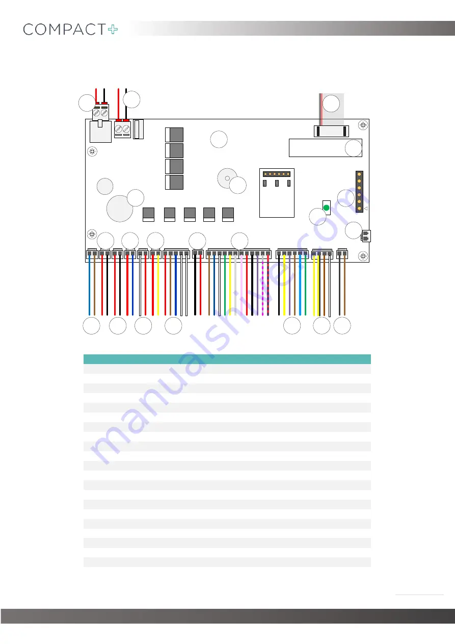
6.
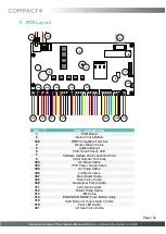
PCB Layout
7
6
8
5
4
302
312
1
306
308
321
309
307
305
311
313
300
314
319
318
348
2
REF
PART DESCRIPTION
1
PCB Board
2
Internal Clock Battery
348
RFID Compatible Terminal
4
Display Ribbon Cable
5
Audible Buzzer
6
PCB Health Check LED
7
Software Update Fob Connection Point
8
Serial Number Text Area
300
AC Motor Cable
302
PCB Power Supply Cable
305
Air Pump Cable
306
Lid Motor Cable
307
Main Water Cable
308
Drain Valve Cable
309
Deodoriser Pump Cable
311
Lid Interlock cable
312
Water Pump Cable
313
IFM Cable
314
‘ENGINEER MODE’ Push Button Cable
318
Start Button & Toggle Switch Cable
319
Floor LED Cable
321
Lid Seal Valve Cable
Summary of Contents for COMPACT+
Page 1: ......

