Vermont Castings Defiant 1610C Homeowner'S Installation And Operating Manual Download Page 7

7

Defiant

®

 1610CE Non-Catalytic Woodburning Stove

30003846

c) Mild steel fluepipes complying with BS 1449: Part 1: 

1991, with a flue wall thickness of at least 3 mm;

d) Cast iron fluepipes complying with BS 41: 1973 

(1998).
Flue Pipes with a spigot and socket joint should be 

fitted with the socket facing upwards, to contain con-

densates and moisture within the flue. Joints should be 

made gas tight using proprietary jointing accessories, 

or, where appropriate, by packing joint with noncombus-

tible rope and fire cement.
Single-wall connectors should be made of 4 gauge 

or heavier steel. Do not use galvanized connector; it 

cannot withstand the high temperatures that can be 

reached by smoke and exhaust gases, and may release 

toxic fumes under high heat.  The connector may be 

15 mm (6”) or 03 mm (8”) in diameter.
If possible, do not pass the chimney connector through 

a combustible wall or ceiling. If passage through a com-

bustible wall is unavoidable, refer to the section on Wall 

Pass-Throughs. Do not pass the connector through an 

attic, a closet or similar concealed space.  The whole 

connector should be exposed and accessible for in-

spection and cleaning.
In horizontal runs of un shielded chimney connector, 

maintain a distance of 76 mm (30”) from the ceiling. 

Keep it as short and direct as possible, with no more 

than two 90° turns. Slope horizontal runs of connector 

upward 6mm per meter (1/4” per foot) going from the 

stove toward the chimney. The recommended maximum 

length of a horizontal run is 914 mm (36”), and the total 

length should be no longer than .4 m (8’). In cathedral 

ceiling installations, extend the prefabricated chimney 

downward to within .4 m (8’) of the stove. This will help 

maintain a good draft by keeping the smoke warm, so 

that it rises readily.
Wear gloves and protective eyewear when drilling, cut-

ting or joining sections of chimney connector.

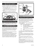
Single-wall chimney connectors

• 

Begin assembly at the flue collar of the stove.  Insert 

the first crimped 

end into the stove’s 

flue collar, and 

keep each crimped 

end pointing toward 

the stove. (Fig. 4) 

Using the holes 

in the flue collar 

as guides, drill 3 

mm (1/8”) holes 

in the bottom of 

the first section of 

chimney connector 

and secure it to the 

flue collar with three #10 x 1/” sheet metal screws. 

Lift off the griddle, and shield the  stove’s surface 

between the griddle opening and the front of the flue 

collar to protect the finish when you drill the front 

hole.

• 

Fasten each joint between sections of chimney 

connector, including telescoping joints, with at least 

three (3) sheet metal screws. The pre-drilled holes in 

the top of each section of chimney connector serve 

as guides when you drill 3 mm (1/8”) holes in the 

bottom of the next section.

• 

Fasten the chimney connector to the chimney.  

Instructions for various installations follow. Figure 6 

illustrates the general layout of chimney connector 

parts.

• 

Be sure the installed stove and chimney connector 

are correct distances from nearby combustible mate-

rials.

NoTe:

 Special slip pipes and thimble sleeves that form 

telescoping joints between sections of chimney con-

nector are available to simplify installations. They often 

eliminate the need to cut individual connector sections. 

Consult your local dealer about these special pieces.

Securing the Single-wall connector to a

prefabricated chimney

Follow the installation instructions of the chimney manu-

facturer exactly as you install the chimney. The manu-

facturer of the chimney will supply the accessories to 

support the chimney, either from the roof of the house, 

at the ceiling of the room where the stove is installed, or 

from an exterior wall.
Special adapters are available from your local dealer to 

make the connection between the prefabricated chim-

ney and the chimney connector. The top of such adapt-

ers attaches directly to the chimney or to the chimney’s 

ceiling support package, while the bottom of the adapter 

is screwed to the chimney connector.
These adapters are designed so the top end will fit out-

side the inner wall of the chimney, and the bottom end 

will fit inside the first section of chimney connector.

Securing the Single-wall connector to a 

Masonry chimney

Both freestanding masonry  chimneys and fireplace 

masonry chimneys may be used for your installation. 

Freestanding installations 

If the chimney connector must pass through a com-

bustible wall to reach the chimney, follow the recom-

mendations in the Wall Pass-Through section that 

follows.  The opening through the chimney wall to the 

flue (the “breech”) must be lined with either a ceramic or 

metal cylinder, called the “thimble”, which is cemented 

ST242

Chimney connector

12/13/99   djt

Flue Gas 

Direction

Toward 

Stove

ST4

Fig. 4 

 Chimney connector.

Summary of Contents for Defiant 1610C

Page 1: ...ed operated and maintained a house fire may result To reduce the risk of fire follow the installation instructions Failure to follow instructions may result in property damage bodily injury or even de...

Page 2: ...mth beauty and comfort in your home At MHSC we share that joy and appre ciation for the hearth We assure you that your cast iron Vermont Castings stove has been made with the utmost care and will prov...

Page 3: ...f heating with wood a home grown fuel with none of the political and economic entanglements of foreign oil Thirteen years later in 1988 Vermont Castings retired the Defiant replacing it with modern wo...

Page 4: ...l Secondary Air Fixed self regulating Ash handling system Removable ash pan Glass panels High temperature ceramic Fig 1 Defiant NC dimensions Drawing Not to Scale D E F I A N T 822 mm 32 6 733 mm 28 6...

Page 5: ...chimney or house fire Follow all instruc tions exactly and do not allow makeshift compro mises to endanger property and personal safety all local regulations including those referring to national and...

Page 6: ...an out door must seal tightly A loose or leaky clean out door can weaken chimney draft caus ing performance problems Prefabricated Chimneys These should be an internal diameter of 150 mm 6 and be of t...

Page 7: ...screws Lift off the griddle and shield the stove s surface between the griddle opening and the front of the flue collar to protect the finish when you drill the front hole Fasten each joint between se...

Page 8: ...nded through the breech to the inner face of the flue liner and cemented securely in place Additional pieces of connector are then attached with sheet metal screws Fireplace Installations The chimney...

Page 9: ...nspector before you begin Also check with the chimney connector manufacturer for any specific requirements Accessories are available for use as wall pass throughs If using one of these make sure it ha...

Page 10: ...terials Both a stove and its chimney connector radiate heat in all directions when operating and nearby combustible materials can overheat dangerously if they are too close to the heat source A safe i...

Page 11: ...inimum distance from stove to movable combus tible materials e g furniture drying clothes etc 1220 mm 48 ST486a Defiant EU Clearance Diagrams 10 06 A B ST486a Fig 11 Minimum clearances Connecting Flue...

Page 12: ...ss rough surfaces can cause the legs to loosen or even break 34 ATTACH LEGS Leg Bolt and Washer ST858 Fig 18 Attach the stove legs ST564 handle holder 12 13 00 Bottom Heat Shield Door Handle Holder Le...

Page 13: ...the two black handles Secure the handle to the stub on the right side of the stove with an 8 32 x 2 slot head machine screw Fig 22 Assemble the Removable Insert Handle The ceramic removable insert ha...

Page 14: ...t will last longer with less heat move the lever toward the rear of the stove A Damper Directs Air Flow Within the Stove The damper handle on the left side of the stove oper ates the damper to direct...

Page 15: ...clear fire viewing and should be left permanently in place Since the andirons may slightly hinder refueling through the front doors most stove owners will prefer the convenience of top loading through...

Page 16: ...outside air vent for appliances with power outputs above 5 kW Always refer to national and local codes to determine your specific requirements The Defiant NC is equipped to deliver outside air for co...

Page 17: ...repeat the procedure as often as necessary if the initial attempt is unsuccessful 4 If your Defiant has been broken in previously us ing Steps 1 3 continue to build the fire gradually Add larger wood...

Page 18: ...e Open the damper Open the griddle or front doors and use a shovel or poker to stir excess ash through the ash slots in the grate down into the ash pan Close the griddle or doors and unlatch the ash d...

Page 19: ...is uses the house as insulation for the flue and allows some heat release into the home An indoor chimney won t lose its heat to the outdoors so it takes less heat from the stove to heat it up and kee...

Page 20: ...nd too vola tile Smoke and combustible gases can gas out from the wood quickly and densely enough to overload the combus tion system If you hear a rumbling or roaring noise like a propane torch from t...

Page 21: ...e glass with water or a cleaner made espe cially for this purpose Do not use abrasive cleaners Use cleaning agents sparingly and be sure to keep them off the outer surfaces of the stove Rinse the glas...

Page 22: ...until the setting is right Replace the Stove Gaskets as Needed Your Defiant uses fiberglass rope gaskets to make a tight seal between some parts With use particu larly on moving parts gaskets can beco...

Page 23: ...echnician 5 16 diameter gasket seals the following parts The lower fireback to the back panel The left and right air plates inner sides All connections between the stove plates The Chimney System Creo...

Page 24: ...e dust from the inner sides of bottom rear or pipe heat shields if your stove is equipped with them Clean surfaces are better heat reflectors than dirty surfaces Touch up the black paint Inspect for a...

Page 25: ...71 73 80 78 68 33 2850 Defiant N parts 11 05 66 62 37 62 11 28 62 59 45 23 45 23 56 46 45 61 60 47 4 1 63 84 36 88 50 92 27 85 91 52 51 26 49 56 83 82 81 91 52 72 74 70 70 29 30 31 79 1 10 9 44 44 57...

Page 26: ...tion Spring 1201846 46 Washer Friction Spring Therm Handle Linkage 1202471 47 Air Plate 30002819 48 Andiron 30002827 49 Control Spacer 1201781 50 Leg Leveller 1201745 51 Ashdoor Handle Shaft 1600622 5...

Page 27: ...CE Part Name Classic Biscuit Bordeaux Chestnut Ebony Midnight Vermont Brown Brown Blue Green Majolica Top 30002834 30002874 30002915 30002926 30002894 30002884 30002937 30004837 Left Side 30002832 300...

Page 28: ...d or any fuel not recommended in the Owners Guide 4 This warranty does not cover a stove repaired by someone other than a Vermont Castings Authorized Dealer 5 Damage to the unit while in transit is no...

Reviews: