


1
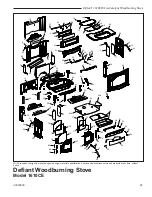
Defiant
®
1610CE Non-Catalytic Woodburning Stove
30003846
Set Up your Stove
Cast iron stoves are heavy, and it will take two to four
people to move your Defiant into position.
Wipe the protective coating of oil from the griddle with a
clean dry rag or a paper towel.
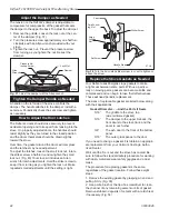
Install the handle on the griddle. Slip the bolt through a
washer, a nylon bushing, then through the handle and
the other bushing, then through the steel spacer and
into the griddle tab. (Fig. 17) Tighten securely.
assembly
install Stove legs
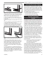
The stove is shipped with the legs attached. In some
instances, the legs may have been removed. Fol-
low these instructions to reattach the legs. Install the
stove legs (Fig. 1) using the hex head bolts from the
parts bag. Use 3/8” washers with all four legs; the door
handle holder installs on the right front leg. Position the
holder so the hole to accept the handle hub faces out
from the right side of the stove. Tighten the bolts firmly.
caUTioN:
Overtightening can strip tapped threads.
NoTe:
When moving the stove, lift the stove to take
weight off the legs whenever possible. Dragging or
sliding the stove, especially across rough surfaces can
cause the legs to loosen or even break.
34
ATTACHLEGS
Leg Bolt and
Washer
ST858
Fig. 18
Attach the stove legs.
ST564
handle holder
12/13/00
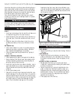
Bottom Heat Shield
Door Handle Holder
Leg Bolt and Washer
ST564
Fig. 19
Handle holder and heat shield positions.
ST536
Fig. 17
Attach the griddle handle.
ST536
Attach
griddle handle
11/00
Bushings
Spacer
Knob
Washer
Bolt
Storing the handle
Use the removable handle to open or close the doors.
After using it, remove the handle so it will not get hot.
Store the handle in the handle holder installed behind
the right front leg. (Fig. 19)
install the bottom heat Shield
NoTe:
The Bottom Heat Shield is required in most
installations. Refer to Floor Protection, Page 10, for
further details.
1. Loosen the four 1/4-0 hex head bolts from the cor-
ners of the ash drop on the stove bottom.
. Align the bottom heat shield holes with the four
bolts. The outside air cutout hole should be toward
the rear of the stove.
3. Pass all four bolts through the large end of the key-
holes and then pulling the shield forward to engage
the smaller ends of the keyhole slots. (Fig. )
4. Attach the heat shield sides by passing the slots
over the bolt heads. Tighten the hex head bolts.
ST857
abottom heat shield
12/05
1/10
ST857
Fig. 20
Attach the optional bottom heat shield.
Bottom Heat Shield


