


13
20306755
30ILDV Series Gas Fireplace Insert
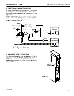
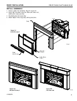
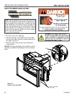
INTAKE MANIFOLD VENT INSTALLATION
Before insert is placed back into fireplace opening, attach intake
flex pipe to intake manifold, located in rear lower left corner with
hose clamp (not supplied) or other approved method.
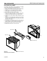
EXHAUST MANIFOLD REMOVAL AND VENT
INSTALLATION
The exhaust manifold is shipped attached to insert. It may be
removed to allow tight installation.
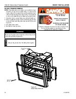
1. Remove glass door assembly following instructions on
Page
18, Figure 16.
2. Lightly tap on flange of exhaust baffle assembly towards you
until disengaged. Remove baffle, manifold and gasket from
unit.
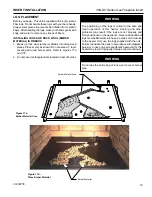
Figure 9
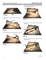
3. Attach the slotted baffle plate.
Figure 10
Figure 9 -
Remove Manifold and Attach to Flex Vent
FP1960
manifold assembly
9/08
Gasket
Manifold
Baffle
Assembly
FP1960
Front View
Side View
Flex Vent
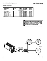
Figure 10 -
Baffle Assembly and Adjustment
FP1961
baffle adjustment
9/08
Loosen Four (4) Screws to Adjust
Bottom View
Closed Position
Bottom View
Open Position
FP1961
30ILDV - Baffle Plate
30ILDV:
Adjust for extended vertical applications.
4. Feed exhaust flex through hole on top of insert and attach to
manifold with hose clamp (not provided) or other approved
methods (check local codes). Insure the gasket is in place
before securing the flex to the manifold.
5. Re-attach exhaust baffle and manifold assembly in reverse
order of Step 2.
6. Re-attach glass door in reverse order.
NOTE:
The 30ILDV has an adjustable baffle and may be adjusted
as needed by loosening four (4) screws.
Figure 10
VENTING INSTALLATION