background image


42 

VeDVR User Guide 

21-0421E rev1.1


5.  In the PTZ control screen, use the direction keys on the DVR control or remote control to adjust the PTZ position. 

Use the “IRIS+”, “IRIS–“, “FOCUS+”, “FOCUS–“, “ZOOM+”, “ZOOM–“ buttons to adjust the iris, focus and zoom. 

6.  When completed, press “ENTER” to return to the “Set Preset” screen. 
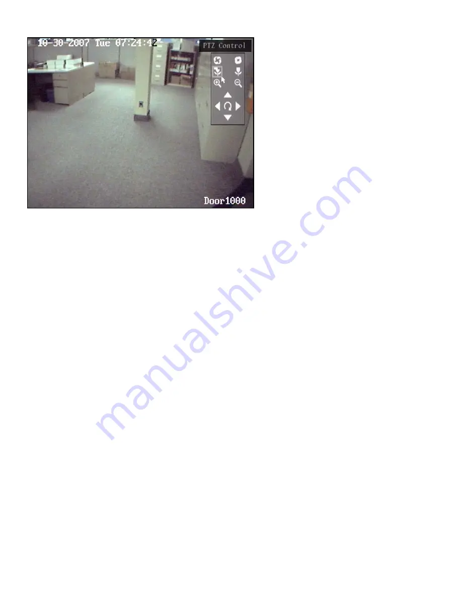
7.  For mouse control, there is a control panel in the upper right corner of the PTZ control screen. The top 2 symbols 

represent the IRIS+ on the left, IRIS– on the right adjustment controls. The next 2 symbols down are for the 
FOCUS+ on the left, FOCUS– on the right adjustment controls. The next 2 down are the ZOOM+ on the left, 
ZOOM– on the right adjustment controls. Rest the mouse pointer on any of these symbols and press and hold the 
left mouse button to make adjustments: increase: +, decrease: –. Below these symbols is the direction control. 
Rest the mouse pointer and left click and hold on any of these directions to maneuver the PTZ camera.  

8.  When completed, right click the mouse to return to the Set Preset screen. 
9.  Press the Save button to save the preset number and its adjustments. 
10.  Repeat this procedure to configure other preset numbers. 
11.  After all preset numbers are configured and Saved, press the Return button to return to the PTZ menu.


Delete a PTZ Preset 


In the Preset menu, enter a preset number in the “Preset:” box and press the “Delete” button. 


After deleting, press Return. 


Summary of Contents for VeDVR

Page 1: ...DVR User Guiderev1 1...

Page 2: ......

Page 3: ...em Setup 7 Main Menu 8 Programming Users and Passwords 8 Add a User 9 Select User Permissions 10 User Rights Description 10 Delete Users 11 Display Menu 12 Image Menu 14 Recording Menu 21 Manual Recor...

Page 4: ...er may void warranties and or cause the specific device to no longer meet local regulatory requirements Copyrights and Trademarks All other trademarks are acknowledged as the property of their respect...

Page 5: ...and if not installed and used in accordance with the instruction manual may cause harmful interference to radio communications Operation of this equipment in a residential area is likely to cause har...

Page 6: ......

Page 7: ...Welcome For further information refer to 21 0420 DVR Installation Guide and 21 0422 DVR PC Software User Guide...

Page 8: ......

Page 9: ...ue modem connection and dial up successful HDD Flashing red reading or writing HDD LINK Blue network connection is OK Tx Rx Flashing Blue data is being transmitted over the network 2 Activity Lights P...

Page 10: ...would send the PTZ camera to Preset 1 SPOT The SPOT button alternates control between the MAIN monitor and the AUX monitor Connect an AUX monitor and turn on the Status Bar A check mark will display o...

Page 11: ...ront panel 17 Lens control in PTZ mode IRIS FOCUS ZOOM for lens control 18 F2 Same as F2 key of front panel IR Remote Control Setup and Configuration Loading the batteries into the Remote Control 1 Re...

Page 12: ...Main Menu Single Camera View Multiple Camera Preview Next Preview PTZ Control Play Event Play Manual Record Close Status Switch Vout Spot button Clicking on the password log in box will display a keyb...

Page 13: ...ircles and each one represents cameras 1 16 on this 16 camera DVR starting from the left The circles change colors to represent the condition of each connected camera When a working camera is connecte...

Page 14: ...ds the selected menu icon The selection square can be moved from one icon to another by using the arrow buttons and When the desired icon is highlighted press ENTER to access the secondary menu Exampl...

Page 15: ...er upper case lower case or symbols Use and to move the cursor Use EDIT to delete the character in front of the cursor Press ENTER or ESC to exit edit mode Button Text Do a special function or enter i...

Page 16: ...Programming Users and Passwords A maximum of 16 users can be assigned with various abilities and permissions 1 From the main menu navigate to the User submenu 2 Press ENTER on the DVR or remote contro...

Page 17: ...recaution 1 Move the cursor to Add and press ENTER 2 Press F3 on the DVR controls or left clicked mouse menu or A on the remote control to change the number keypad to the desired function I e Number U...

Page 18: ...be assigned 3 If more advanced rights need to be assigned use to navigate to the Set Permissions button in the Add Delete screen and press ENTER or left click a mouse on it to select it Operational ri...

Page 19: ...CTRL DVR RS 232 transparent channel function User s PC MAC address This is the MAC address of the PC that will access the DVR If the MAC address is used only the PC with this MAC address will be able...

Page 20: ...D is used to identify the DVR to the IR Remote Control Set this number from 01 to 255 Set the Device ID of the IR Remote Control to the same number If there are multiple DVR s in a room the remote con...

Page 21: ...DVRs Choose from 1 3 1 1 or 3 1 or No Transparency to determine the visibility of the Setup Menu with the Preview Mode screen 1 Highlight Menu Transparency 2 Use to set the desired menu visibility VG...

Page 22: ...et display properties for Camera Name Define a name for each camera NOTE the camera s name cannot be copied 1 Select one camera 2 Highlight the Name edit box 3 Press EDIT 4 Press F3 on the DVR control...

Page 23: ...ght side of OSD and press ENTER 2 The OSD position setup screen will display This screen shows the current camera live preview with a grid overlaid on top There are 22x15 small panes for the NTSC form...

Page 24: ...the mask area is set press EDIT or right click for mouse selections confirm cancel clear 6 Press ESC to cancel the mask area 7 After the area is setup press ENTER to return Image Menu Press ESC to ab...

Page 25: ...arm in Schedule Setup a schedule to determine when the Video Signal Loss Alarm will be activated Ensure that adequate time periods are set to avoid missing possible occurrences When a Video Loss Alarm...

Page 26: ...tion areas must be defined so the DVR will respond to motion detected in those areas Highlight the Area button to the right of the Mot Det enable 9 symbol in the Camera Input Adjustment screen 2 Press...

Page 27: ...ion area is setup press EDIT the yellow square will appear again Repeat the above procedure to setup another motion area Clear the Motion Area 1 Move the yellow square to the beginning position of the...

Page 28: ...enable the channel The x changes to 9 to enable the function NOTE Recording must be enabled and the Recording Type must be set to Motion Detection Motion Alarm or Motion or Alarm in order for the cam...

Page 29: ...the selections and return to the Image menu Pressing cancel will not save the changes and will return to the Image menu This procedure can be repeated to setup motion detection for other cameras Thes...

Page 30: ...the camera number displays This name is defined in the Image Menu Stream Type Audio Video Use to record audio and video Video Use to record video only NOTE If Audio recording is disabled the Remote St...

Page 31: ...hange the x to a check mark 9 Press the Schedule button All Day Recording selections 1 Use ENTER or EDIT to enable the recording function and change the x to a check mark 9 2 Press the Schedule button...

Page 32: ...ype for each period The Record Type options are the same as the previous All Day Recording selection options Cont HQ Continuous High Quality default selection Cont LQ Continuous Low Quality Cont HQIEv...

Page 33: ...o and press Copy Press Confirm to save changes or Cancel to not save changes and return to the Main Menu Manual Recording Requirements to Enable Manual Recording 1 A user who attempts to turn cameras...

Page 34: ...el playback a second channel can not be selected If it does feature a second channel then both channels can be played at the same time Select a second camera channel to play back with the main selecte...

Page 35: ...key The DVR will search and list the matched files To begin playback on a file after the search is complete use the direction arrows to navigate to the list and then use up and down to select the fil...

Page 36: ...sing the button a second time 30 seconds into a clip will transfer the view to a prior clip in the results list or back to the results list if this was the first clip played or only clip in the list W...

Page 37: ...mouse on either image to just show that image or left click the single image to go back to 2 channel viewing again SmartSearch Motion History SmartSearch acts the same as Motion History in the DVR s P...

Page 38: ...tinuous motion inside the selected search area the resulting clips can be as long as the maximum clip length of 128MB SmartSearch will find any type of motion regardless of what caused the motion Exam...

Page 39: ...10 100 baseT Ethernet network connection PP0E broadband or PSTN narrow band dialup To remotely access the DVR the network selections must be made here Highlight the Network icon in the Main Menu and...

Page 40: ...ol and works only if the network to which the DVR and the Remote Station software are connected supports Multicast Multicast traffic will not pass through routers and gateways unless the local network...

Page 41: ...tach JPEG images to emails that contain camera specific event information i e signal loss motion view tampering There is a limit of how many JPEG images can be emailed at the same time When multiple e...

Page 42: ...the mouse to change the selection 4 Press ENTER to save a selection and return to the Image Menu 5 After making changes press Confirm to save the changes or Cancel to not save the changes Enable RSE...

Page 43: ...Use to change the selection Left click the mouse to change the selection 4 Press ENTER to save a selection and return to the Image Menu 5 After making changes press Confirm to save the changes or Canc...

Page 44: ...setup for each day of the week The schedule of one day can be copied to another NOTE Time periods in one day cannot be repeated 1 When a Motion Alarm has occurred during the defined schedule the DVR w...

Page 45: ...PTZ Menu for more information Enable Cruise Change the selection to 9 to enable Sequence Refer to the PTZ Menu for more information Press the Confirm button to save and return to the Alarms Menu Pres...

Page 46: ...utton on the right side of the Alarm Out Time press ENTER on the DVR controls or remote control or left click a mouse to display the Schedule menu for the associated output Define the Alarm Output Sch...

Page 47: ...age Menu 5 After making changes press Confirm to save the changes or Cancel to not save the changes Exception Select from the following exceptions Hard Disk Full Hard Disk Error Network Failure Illega...

Page 48: ...IT to change a selection 3 Use to change the selection Left click the mouse to change the selection 4 Press ENTER to save a selection and return to the Image Menu 5 After making changes press Confirm...

Page 49: ...p M_MV2050 TIANDI DM DynaColor SAE_QUICK TWHC HD600 RED_APPLE USNT JC 4116 NK08G KALLATENVD2200PS Pelco d WX NOTE In the DVR PTZ menu if the Pelco P protocol is selected when the PTZ address is config...

Page 50: ...2 down are the ZOOM on the left ZOOM on the right adjustment controls Rest the mouse pointer on any of these symbols and press and hold the left mouse button to make adjustments increase decrease Belo...

Page 51: ...T or left click on the selection for a mouse menu to enter the following Cruise Point Each Sequence is comprised of a Cruise Point number Enter a Cruise Point number Preset Enter a Preset number from...

Page 52: ...il pressing the StopSeq button to stop it 6 Press the Return button to return to the PTZ menu Press Confirm to save changes or Cancel not to save changes and return to the Main Menu Copy to In the PTZ...

Page 53: ...d Rate 9600 default selection 19200 38400 57600 76800 115 2k 50 75 110 150 300 600 1200 2400 4800 Data Bits 8 bit default selection 5 6 7 Stop Bits 1 bit default selection 2 Parity No Parity default s...

Page 54: ...f the Remote PC modemInit Not used Press Confirm to save changes or Cancel not to save changes and return to the Main Menu Preview Menu Customize the regular DVR screen view referred to as Preview Mod...

Page 55: ...Press EDIT to convert the up down arrow buttons to increase or decrease the number order in each square or enter a number using the keypad When the number selection in the square is complete press EN...

Page 56: ...o Length Info Start end position and length of a credit card number Enter the Offset and Length Card Number Info Start end position and length of a transaction type Enter the Offset and Length Operati...

Page 57: ...changes or Cancel not to save the changes and return to the Main Menu Obtain By String from Serial Port ATM Type Select the ATM machine brand from the following available NCR default OLIVETTI IBM GDYT...

Page 58: ...ough the RS 232 port based on the manufacturer s communication protocol Press Confirm to save changes or Cancel not to save the changes and return to the Main Menu Utilities Menu There are several sel...

Page 59: ...ctions in the screens 5 Press ENTER or left click a mouse to execute a selection Tools Selections Import export of configurations with USB View the Hard Disk Drive Change Information Para meters In Ou...

Page 60: ...mation will appear as follows This information is not available in the Remote Station software The purpose of this function is to act as an alert of unexpected changes to the DVR s HDD configuration T...

Page 61: ...Upgrade icon in the pop up dialog Select either FTP or USB Update Mode FTP Mode FTP Server s IP Address Input the FTP server s IP address and press ENTER or right click the mouse menu The DVR will con...

Page 62: ...R hard drive connections are Hard Drive Connection Device 1 Back up to an external device E Sata connector on the back of the DVR 2 Panasonic SATA DVD Writer Compatible 8 cm DVD discs Ritek DVD R Mits...

Page 63: ...ions to search By Type By Date By Type Time By Type Type is divided into Major Type and Minor Type Major Type includes Operation Alarm Exception and All The Minor Types become active for certain Major...

Page 64: ...56 VeDVR User Guide 21 0421E rev1 1 Press the MoreInfo rmation button again for more search information...

Page 65: ...21 0421E rev1 1 VeDVR User Guide 57 System Information Press the System Info icon to view the DVR system information...

Page 66: ...Model Description Video Input Standard BNC 1 Audio Input Standard BNC Main Video Output Connect CCTV monitor output video and OSD menus 2 Main Audio Output Local audio output Auxiliary Video Output Sp...

Page 67: ...004 Alarm Inputs 4 alarm sensor inputs Use G connection on alarm block as common RS 485 PTZ connection Using T T to connect PTZ Optional Keyboard Using K B for DS 1000KI keyboard with PTZ joystick and...

Page 68: ...tion Area Setup 18 Motion Detection Level 18 Multicast IP 32 NIC Type 31 NTSC 13 OSD On Screen Display 15 Output Alarm Time Schedule 38 Output Delay after Alarm 37 PAL 13 Password Defaults 7 PC MAC Ad...

Page 69: ......

Reviews: