


4.7.3
Test
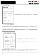
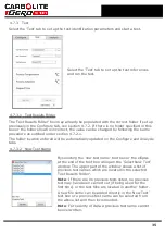
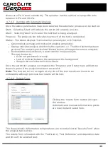
Select the 'Test' tab to set up the test identification parameters and start a test.
Select the 'Test' tab to set up the test references
and run the test.
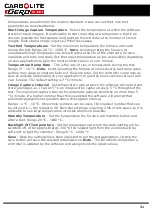
4.7.3.1
Test Results Folder
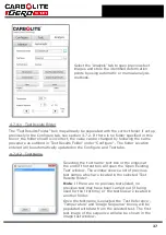
The 'Test Results Folder' box may already be populated with the correct folder if set up
previously in the Configure tab, see section 4.7.2. If there is no folder specified in this
box or the folder shown is incorrect, the value can be changed by following the same
procedure as outlined under section 4.7.2.1.
The folder location entered will be automatically updated on the Configure and Analysis
tabs.
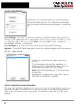
4.7.3.2
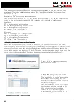
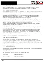
New Test Name
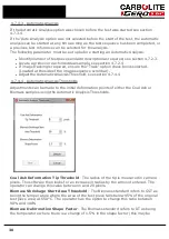
By selecting the 'new test name' text box or the ellipsis
at the end of the text box will open the 'Select New Test'
window. The upper part of the window shows a list of
previous test names which are located in the selected
'Test Results Folder'.
Note
: If there are no previous tests listed, no previous
test may have been carried out (if being used for the
first time) or the test files are located in another folder.
A new file name can be added directly in the 'New Test'
text box or a previous test name can be selected from
the above list and then incremented.
Note
: For security of data a previous test name cannot
be overwritten.
35
Summary of Contents for CARBOLITE GERO CAF G5
Page 63: ...Fig 3 Front Tube Seal Assembly Fig 4 Door Arm Assembly 63 ...
Page 64: ...Fig 5a Camera Mounting Bracket Fig 5b Lens and Camera Assembly 64 ...
Page 65: ...Fig 5c Sliding the Camera Mounting Bracket Assembly onto the Door Arm 65 ...
Page 66: ...Fig 5d Securing the Camera Mounting Bracket Assembly to the Door Arm 66 ...
Page 67: ...Fig 5e Mounting the Lens and Camera Assembly 67 ...
Page 68: ...Fig 5f Lens and Camera Assembly in Position 68 ...
Page 69: ...Fig 6a Rear View of the Standard CAF G5 Furnace Showing Brick Box Assembly 69 ...
Page 71: ...Fig 7 Front Tube Seal Position 71 ...
Page 72: ...Fig 8 Tube End Seal Assembly Tightening Sequence Fig 9 Work Tube Front Support 72 ...
Page 73: ...Fig 10 Fitting the Door Arm Assembly Fig 10a Adjusting the Door Arm Assembly 73 ...
Page 74: ...Fig 11a Furnace Case and Controls 74 ...
Page 75: ...Fig 11b Gas Inlet Pipe Fig 12 Positioning the Furnace 75 ...
Page 77: ...Fig 13c Loading Samples into the Work Tube 77 ...
Page 78: ...Fig 16 File Folder 78 ...
Page 79: ...Fig 17 Door Arm Assembly Exploded View 79 ...
Page 82: ...SST DT HT FT Fig 18 Report Sheet Page 2 Side View Plan View Fig 19 Formed Wire Sample 82 ...
Page 83: ...Fig 20 Sample Carrier Sample Tiles and Sample Positions 83 ...
Page 84: ...Fig 21a Coal and Coke Test Piece Mould Fig 21b Biomass Test Piece Mould and Hand Press 84 ...
Page 85: ...Fig 22 Sample Loading Tool Fig 23 Camera Ethernet Connection 85 ...
Page 86: ...Fig 24 LED Driver Connection 86 ...
Page 87: ...Notes Service Record Engineer Name Date Record of Work ...


