background image

Safety  De cal  Lo ca tions

SAFETY

B-3

Summary of Contents for VR300

Page 1: ...REVISED 02 03 20 09 10040 VENTRAC VR300 OWNER OPERATOR S MANUAL PARTS LIST Venture Products Inc Orrville OH ...

Page 2: ...l and Serial numbers Please fill in the following information for future reference See picture below to find the location of the identification number Record them in the spaces provided below Date of Purchase Month _________________ Day ___________ Year ___________________ Dealer _______________________________________________________________________ Dealer Address ________________________________...

Page 3: ...ecautions General Maintenance D 1 Maintenance Schedule D 2 Oils Fuel Tank D 3 Tires Parking Brake Drive Belt Adjustments D 4 Drive Chain Neutral Safety Switch Ground Clearance Adjustments D 5 Electrical Schematic D 6 PARTS ILLUSTRATED DRAWINGS SECTION E Chair Compartment E 1 2 Tailgate Mechanism E 3 4 Brake Mechanism E 5 6 Pump Controls E 7 8 Drive Wheel E 9 10 Engine E 11 12 Handle Bar Controls E...

Page 4: ...hes Overall Width 42 5 inches Overall Length 75 inches Chair Compartment Length 50 inches Chair Compartment Width 32 inches Ground Clearance 1 4 inches Weight 320 lbs Weight Capacity 400 lbs Tires Front 16 x 7 5 x 8 Back 15 x 4 0 x 8 Venture Products Inc reserves the right to change these specifications without notice ...

Page 5: ...f not avoided could result in death or serious injury Indicates an imminently hazardous situation which if not avoided will result in death or serious injury This signal word is limited to the most extreme cases The engine exhaust from this product contains chemicals known to the State of California to cause cancer birth defects or other reproductive harm Diesel engine exhaust and some of it s con...

Page 6: ...issing contact your dealer promptly for replacements SAFETY Decal Page Location Description Part Number A B 3 Caution Read Owner s Manual 00 0135 B B 3 Danger Pinching Hazard 00 0102 C B 3 Warning Battery Decal 00 0124 D B 3 Read Owner s Manual 00 0217 E B 3 Parking Brake Decal 00 0129 A B C E D ...

Page 7: ...Safety Decal Locations SAFETY B 3 ...

Page 8: ...e clear of the tractor and attachment before operating Be especially careful and observant if other people are present Never assume that bystanders will remain where you last saw them Always look in the direction the tractor is moving Never direct the discharge of any attachment in the direction of people animals buildings vehicles or objects of value Stop operation immediately at any sign of equi...

Page 9: ...ment and could cause serious injury or death A safety switch requires the Speed Control Lever to be in the neutral position to start the engine Vary vehicle speed with the Speed Control Lever not with the engine speed Always maintain adequate engine speed during operation of the VR300 Always check to the rear before moving the VR300 in reverse Never allow riders on the VR300 Never attempt to make ...

Page 10: ... removed from lever Light Switch For headlight Figure 1 Switch Panel Figure 2 Throttle Lever Throttle Lever To increase engine speed move lever to the right To decrease en gine speed move lever to the left Figure 3 Chair Compartment Lever Chair Compartment Lever To raise tail gate pull handle back To lower tailgate push handle forward ...

Page 11: ...Parking Brake Lever Pull the lever back to engage the parking brake Push the lever forward to release the parking brake The parking brake is located near the left rear of the engine To adjust the parking brake see page D 4 Coast Lever The coast lever located near the right front of the engine is used to dis engage the hydrostatic drive which allows the unit to freewheel During normal opera tion th...

Page 12: ...til contact is made between chair and front stops 4 Pull back on chair compartment lever to close the tailgate This helps secure the wheelchair between the front stops and tailgate 5 The tailgate page E 3 and front stops page E 1 are adjustable to accommodate most wheelchairs If proper adjustment cannot be made in securing the wheelchair additional stops or lockdowns of the owner s choice must be ...

Page 13: ...rease or decrease the speed of the tractor by movement of the speed control lever 5 Make allowances in speed selection for hills slopes and rough terrain If the operator is uncomfortable or unsure of the unit s stability the operator should cease operation in that condition 6 The hydrostatic transmission provides a braking action when the speed control lever is returned to neutral 7 After operatio...

Page 14: ...areas while the engine is running or immediately after it is turned off Never operate the VR300 withheat shields or guards removed General Maintenance 1 Review Operator s Manual periodically 2 Keep the VR300 clean 3 Check all tires for proper inflation See page D 4 4 Check that the battery is securely held in place and the terminals are free of corrosion Properly clean and lightly lubricate batter...

Page 15: ...nance schedules MAINTENANCE D 2 Spring Startup B Starting Engine 5 Hours 50 Hours Full Service 100 Hours 200 Hours 300 Hours 400 Hours Full Service 500 Hours Review Engine Operators Manual X X X X X X X X X Review 300 Operators Manual X X X X X X X X X Check for Oil Leaks X X Check for Loose Nuts or Bolts X X Check Belt Chain X X Check Tires X X Check All Oil Levels X X Clean Cooling Shrouds Fins ...

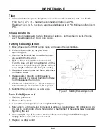
Page 16: ...ils on the engine oil level type of oil recommended and changing the engine oil Hydrostatic Oil The importance of checking and maintaining the proper oil level in the hydrostatic drive cannot be overemphasized Check oil as follows Refer to page D 2 for schedule 1 Make sure the engine is stopped the hydrostatic oil is cool and the VR300 is on a level surface 2 Locate the oil level check line on pla...

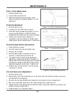
Page 17: ...acquired Note Maintain equal length of threads into both yoke ends 5 Reconnect yoke to brake rod Move brake lever to observe travel 6 Repeat steps 3 through 5 until brake lever snaps securely over center pushing the brake rod firmly against the front tire 7 Check and reinstall lock nut If lock nut can be turned without a wrench it must be replaced 8 Re tighten the jam nuts on the yoke ends Drive B...

Page 18: ... above the drive tire 5 The switch button must be fully depressed against the neutral lever while in neutral To adjust loosen bolt holding safety switch bracket and slide the bracket until safety button is fully depressed against neutral lever Tighten bolt 6 Replace drive shield and test Unit must start only while in neutral Ground Clearance Adjustment 1 Remove ignition key 2 Raise back end of rea...

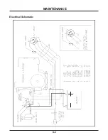
Page 19: ...Electrical Schematic MAINTENANCE D 6 ...

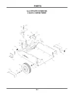
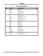
Page 20: ...PARTS E 1 ILLUSTRATED DRAWING CHAIR COMPARTMENT ...

Page 21: ...y Wide Tire 2 9 90 1244 3 4 10 x 5 1 2 Bolt 2 90 1252 3 4 10 x 6 1 2 Bolt Wide Tire 2 10 60 0640 Left Fender 1 11 00 0189 Decal Ventrac 2 12 64 0632 Left Wheel Guide 1 13 64 0633 Wheel Stop 2 14 47 0110 Reflector amber 2 15 99 A08 1 2 13 Lock Nut 1 16 94 08 1 2 USS Flat Washer 2 17 64 0628 Pivot Spacer 1 18 90 0848 1 2 13 x 6 Bolt 1 19 99 SF05 5 16 18 Flange Nut 8 20 99 SF0504 5 16 18 x 1 2 Flange...

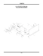
Page 22: ...PARTS E 3 ILLUSTRATED DRAWING TAILGATE MECHANISM ...

Page 23: ...lange Bolt 2 6 42 0379 Tailgate Front Link 1 7 41 0054 3 4 x 6 1 2 Extension Spring 1 8 47 0001 Knob 1 9 99 SF04 1 4 20 Flange Nut 2 10 90 0408 1 4 20 x 1 Bolt 1 11 85 B0068 3 8 x 1 2 Nylon Bushing 2 12 90 0618 3 8 16 x 2 1 4 Bolt 1 13 40 0230 Tailgate Control Lever 1 14 64 0629 Lever Anchor 1 15 99 SF0506 5 16 18 x 3 4 Flange Bolt 3 16 99 SF05 5 16 18 Flange Nut 3 17 95 05 5 16 SAE Flat Washer 3 ...

Page 24: ...PARTS E 5 ILLUSTRATED DRAWING BRAKE MECHANISM ...

Page 25: ... 3 4 Flange Bolt 1 7 43 006 3 8 Spherical Rod End 2 8 90 0610 3 8 16 x 1 1 4 Bolt 2 9 93 06 3 8 24 Nut 2 10 99 j0668NF Brake Link 1 11 99 A06 3 8 16 Lock Nut 1 12 41 0052 3 8 x 3 3 4 Extension Spring 1 13 90 0508 5 16 18 x 1 Bolt 1 14 99 SF05 5 16 18 Flange Nut 4 15 64 0636 Right Handle Bar Mounting Plate 1 16 99 SF0506 5 16 18 x 3 4 Flange Bolt 2 17 42 0377 Brake Rod 1 18 64 0689 Left Handle Bar ...

Page 26: ...PARTS E 7 ILLUSTRATED DRAWING PUMP CONTROLS ...

Page 27: ...13 95 06 3 8 SAE Flat Washer 12 14 99 SF06 3 8 16 Flange Nut 7 15 93 06 3 8 24 Nut 4 16 96 06 3 8 Lock Washer 2 17 43 006S 3 8 Studded Spherical Rod End 2 18 42 0382 Shift Link Rod 1 19 99 A05 5 16 18 Lock Nut 2 20 95 06 5 16 SAE Flat Washer 4 21 55 0022 Ball Bearing 2 22 90 0508 5 16 18 x 1 Bolt 2 23 99 A06 3 8 16 Lock Nut 1 24 64 0635 Pump Arm 1 25 90 0622 3 8 16 x 2 3 4 Bolt 4 26 90 0406 1 4 20...

Page 28: ...PARTS E 9 ILLUSTRATED DRAWING DRIVE WHEEL ...

Page 29: ...ock Washer 1 8 83 5015E08 Idler Sprocket 1 9 94 08 1 2 USS Flat Washer 4 10 90 0816 1 2 13 x 2 Bolt 1 11 55 FB16016 1 Flange Block Bearing 2 12 99 SF0508 5 16 18 x 1 Flange Bolt 4 13 99 SF05 5 16 18 Flange Nut 4 14 50 0048 Drive Wheel Axle 1 15 53 0082 Drive Wheel Assembly 1 16 99 SF04 1 4 20 Flange Nut 4 17 99 E0001 1 2 20 Lug Nut 4 18 44 0153 Mud Flap 1 19 99 SF0404 1 4 20 x 1 2 Flange Bolt 4 20...

Page 30: ...PARTS E 11 ILLUSTRATED DRAWING ENGINE ...

Page 31: ...hine Screw serial 1010 1074 1 5 99 SF05 5 16 18 Flange Nut 12 6 99 E0035 10 32 Flange Nut serial 1075 1 7 64 0637 Engine Mount Plate 1 8 99 K0062 10 32 x 1 2 Machine Screw serial 1075 1 9 29 N0432G 1 4 x 4 Galvanized Pipe Nipple 1 10 29 C04 1 4 Pipe Cap 1 11 99 SF06 3 8 16 Flange Nut 4 12 99 SF0606 3 8 16 x 3 4 Flange Bolt 4 13 83 AS2512 Pulley 1 14 85 K0310 3 16 x 1 1 4 Key 1 15 05 0039 Isolator ...

Page 32: ...PARTS E 13 ILLUSTRATED DRAWING HANDLE BAR CONTROLS ...

Page 33: ...0106 Throttle Cable 1 9 99 E0035 10 32 Flange Nut 6 10 60 0642 Switch Box Cover 1 11 99 SF06 3 8 16 Flange Nut 4 12 00 0129 Decal Parking Brake 1 13 99 SF0606 3 8 16 x 3 4 Flange Bolt 4 14 31 0030 Dummy Plug serial 1001 1068 1 15 31 0022 Light Switch serial 1001 1068 1 16 13 0043 Ignition Switch serial 1001 1068 1 17 13 0036 Ignition Key serial 1001 1068 1 18 13 0078 Ignition Switch serial 1069 1 ...

Page 34: ...PARTS E 15 ILLUSTRATED DRAWING COAST LEVER ELECTRICAL PARTS ...

Page 35: ...t 2 4 99 K0062 10 32 x 1 2 Machine Screw 2 5 30 0149 15 Amp Circuit Breaker 1 6 99 SF05 5 16 18 Flange Nut 1 7 99 SF04 1 4 20 Flange Nut 3 8 99 E0035 10 32 Flange Nut 2 9 90 0410 1 4 20 x 1 1 4 Bolt 1 10 94 04 1 4 USS Flat Washer 2 11 40 0236 Coast Lever 1 12 90 0404 1 4 20 x 1 2 Bolt 1 13 41 0039 Compression Spring 1 14 99 A04 1 4 20 Lock Nut 1 ...

Page 36: ...PARTS E 17 ILLUSTRATED DRAWING SHIELDS BATTERY ...

Page 37: ...lt 6 5 00 0134 Decal 300 2 6 00 0119 Decal Front Wheel Drive 2 7 90 0406 1 4 20 x 3 4 Bolt 6 8 94 04 1 4 USS Flat Washer 2 9 64 0634 Battery Hold down 1 10 34 1001 1001 Negative Battery Cable Assembly 1 11 34 1003 1006 Positive Battery Cable Assembly 1 12 33 0026 Battery 1 13 64 0630 Battery Box 1 14 00 0124 Decal Warning Battery Gases 1 15 99 SF0506 5 16 18 x 3 4 Flange Bolt 4 16 00 0102 Decal Da...

Page 38: ...PARTS F 1 ILLUSTRATED DRAWING GUN RACK ...

Page 39: ... A04 1 4 20 Lock Nut 1 3 60 0647 Gun Rack 1 4 99 K0066 1 4 20 x 1 2 Machine Screw 6 5 06 0042 46 25IN Trim Loc x 46 1 4 2 6 99 SF0606 3 8 16 x 3 4 Flange Bolt 2 7 64 0640 Mounting Bracket 2 8 94 06 3 8 USS Flat Washer 6 9 99 SF04 1 4 20 Flange Nut 6 10 99 SF06 3 8 16 Flange Nut 2 ...

Page 40: ...PARTS F 3 ILLUSTRATED DRAWING BRAKE LEVER EXTENSION ...

Page 41: ...9 SF0606 3 8 16 x 3 4 Flange Bolt 1 6 90 0610 3 8 16 x 1 1 4 Bolt 1 7 43 006 3 8 Spherical Rod End 2 8 93 06 3 8 24 Nut 2 9 99 J0696NFZ Brake Link 1 10 99 SF06 3 8 16 Flange Nut 5 11 99 A06 3 8 16 Lock Nut 1 12 41 0052 3 8 x 3 3 4 Extension Spring 1 13 90 0512 5 16 18 x 1 1 2 Bolt 1 14 99 SF05 5 16 18 Flange Nut 2 15 64 0662 Mounting Plate 1 16 95 06 3 8 SAE Flat Washer 1 ...

Page 42: ...PARTS F 5 ILLUSTRATED DRAWING RAMP TAILGATE LEVER EXTENSION ...

Page 43: ...0618 3 8 16 x 2 1 4 Bolt 2 4 85 B0068 3 8 x 1 2 Nylon Bushing 4 5 90 0610 3 8 16 x 1 1 4 Bolt 4 6 42 0384 Link 1 7 99 SF0606 3 8 16 x 3 4 Flange Bolt 1 8 47 0001 Knob 1 9 40 0237 Control Lever 1 10 99 SF04 1 4 20 Flange Nut 2 11 41 0054 3 4 x 6 1 2 Extension Spring 1 12 90 0408 1 4 20 x 1 Bolt 1 13 64 0663 Mounting Plate 1 ...

Page 44: ...PARTS F 7 ILLUSTRATED DRAWING TACHOMETER HOUR METER ...

Page 45: ...ART NO DESCRIPTION QTY 1 13 0031 Digital Tachometer Hour Meter 1 2 64 0652 Mount Bracket 1 3 99 E0035 10 32 Flange Nut 4 4 99 K0062 10 32 x 1 2 Machine Screw 4 5 99 B0051 10 Flat Washer 2 6 30 0130 18IN 1 4 Corrugated Loom x 18 1 Not shown ...

Reviews: