


OPERATION
C-2
Speed Con trol / For ward/Re verse Le ver
The speed con trol levercontrols the for -
ward/re verse mo tion of the unit. Pushing
for ward or back ward beyond the neu tral
po si tion ini ti ates move ment. The fur ther the
speed con trol le ver is pushed from neu tral
the faster the unit will go. Pulling the le ver
back to neu tral de creases your speed, as
well as pro vid ing a brak ing ac tion.
Braking
- The hy dro static trans mis sion pro -
vides a brak ing ac tion when the speed
con trol le ver is re turned to neu tral.
Fig ure 4 - Speed Con trol Lever
Fig ure 5 - Parking Brake Lever
Parking Brake Le ver
- Pull the le ver back to
en gage the park ing brake. Push the le ver
for ward to re lease the park ing brake. The
park ing brake is lo cated near the left rear
of the en gine.
To ad just the park ing brake, see page D-4.
Coast Le ver
- The coast le ver (lo cated near
the right front of the en gine) is used to dis -
en gage the hy dro static drive, which al lows
the unit to free wheel. Dur ing nor mal op er a -
tion, the le ver is in the for ward po si tion, en -
gag ing the drive. If it is nec es sary to push
or tow the unit, first pull the le ver back,
then down, lock ing it in place be hind the
bolt head.
CAU TION:
The le ver must never re main in the
dis en gaged po si tion, ex cept dur ing ac tual
free wheel ing. Never at tempt to op er ate the
unit while drive is dis en gaged.
Fig ure 6 - Coast Lever
Summary of Contents for VR300
Page 7: ...Safety Decal Locations SAFETY B 3 ...
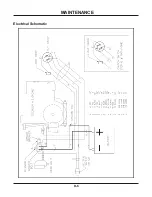
Page 19: ...Electrical Schematic MAINTENANCE D 6 ...
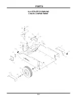
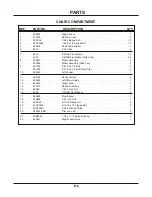
Page 20: ...PARTS E 1 ILLUSTRATED DRAWING CHAIR COMPARTMENT ...
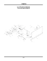
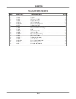
Page 22: ...PARTS E 3 ILLUSTRATED DRAWING TAILGATE MECHANISM ...
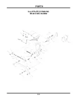
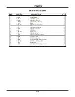
Page 24: ...PARTS E 5 ILLUSTRATED DRAWING BRAKE MECHANISM ...
Page 26: ...PARTS E 7 ILLUSTRATED DRAWING PUMP CONTROLS ...
Page 28: ...PARTS E 9 ILLUSTRATED DRAWING DRIVE WHEEL ...
Page 30: ...PARTS E 11 ILLUSTRATED DRAWING ENGINE ...
Page 32: ...PARTS E 13 ILLUSTRATED DRAWING HANDLE BAR CONTROLS ...
Page 34: ...PARTS E 15 ILLUSTRATED DRAWING COAST LEVER ELECTRICAL PARTS ...
Page 36: ...PARTS E 17 ILLUSTRATED DRAWING SHIELDS BATTERY ...
Page 38: ...PARTS F 1 ILLUSTRATED DRAWING GUN RACK ...
Page 40: ...PARTS F 3 ILLUSTRATED DRAWING BRAKE LEVER EXTENSION ...
Page 42: ...PARTS F 5 ILLUSTRATED DRAWING RAMP TAILGATE LEVER EXTENSION ...
Page 44: ...PARTS F 7 ILLUSTRATED DRAWING TACHOMETER HOUR METER ...


