GENERAL OPERATION
Operation - 17
Transport of V-blade
Transport the V-blade with the power unit front hitch
and V-blade raised to reduce wear of the machine
and to prevent the V-blade from catching on high
spots in the ground, rocks, or other obstacles. Travel
slowly when transporting over undulating or rough
surfaces to maintain control of power unit and to
reduce shock to the machine.
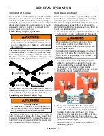
Blade Wing Angle Adjustment
When blade wings are being angled to the back,
pinch points are created. Make sure there are no
people or objects present between the blade and
the power unit.
The blade wings can be angled left or right to push
material to the sides. The blade wings can be swept
back for single pass clearing of sidewalks and paths.
The blade wings can be swept forward to clear areas
without the need for repeated clean up passes.
Angled Right
Angled Left
Swept Back
Swept Forward
Use the 12 volt switch on the power unit to select the
desired blade wing and move the secondary S.D.L.A.
lever to the left or right to angle the blade wing.
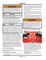
Resetting the Blade Safety Trip
Pinching Hazard
If V-blade trips, the blade may suddenly return to
the operating position. Do not leave the operator’s
seat or attempt to reset the blade manually.
If the V-blade safety trip is activated but does not reset
itself, do not attempt to raise the V-blade. Slowly back
the power unit away from the obstacle. The blade will
return to the operating position when it is moved away
from the obstacle on which it is caught.
Skid Shoe Adjustment
Skid shoes are provided to keep the cutting edge off
the surface to be cleared, especially when clearing
snow from gravel driveways or roadways.
The skid shoe height is determined by the placement
of spacer washers between the skid shoe and the
skid shoe mount. Extra spacer washers are stored on
top of the skid shoe mount.
1. Determine the number of spacer washers that need
to be moved to reach the desired skid shoe height.
2.
When making adjustments with the V-blade
in the raised position, the V-blade must be
securely supported under the cutting edge with
blocks or jack stands.
Hydraulic drift or accidental release of hydraulic
pressure could allow the V-blade to lower and
trap a person or appendage, if the V-blade is not
securely supported.
Raise the V-blade to the highest position and
adjust the blade wing angle until both wings are
perpendicular to the power unit. Support the V-
blade securely with blocks or jack stands.
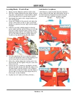
3. Remove the lynch pin (A) and the spacer washers
(B) from the top of the skid shoe mount.
4.
A
B
B
Add or remove
washers to ad-
just skid shoe
height.
Remove the skid shoe from the bottom of the
skid shoe mount. Add or remove spacer washers
to reach the desired skid shoe height and insert
the skid shoe into the skid shoe mount. Place
any extra spacer washers on top of the skid shoe
mount and fasten the skid shoe in place with the
lynch pin. Both the right and left skid shoes should
be set at the same height.
5. Remove blocks or jack stands and lower the V-
blade to the ground.


