SERVICE
Service - 19
Leveling Blade - Front to Rear
1. Make sure the blade is level from side to side.
2. With the V-blade attached to the power unit and
the power unit parked on a level surface, adjust
both wings back into the swept back position.
3. Disengage the power unit’s weight transfer sys-
tem (if equipped).
4. Lower the V-blade to the ground and place the
power unit’s primary S.D.L.A. lever in the float
position by pushing it to the right until the detent
engages.
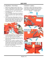
5. Check to see if the cutting edges are making
even contact with the ground. If they are not mak-
ing even contact, loosen the jam nut (A) on the
adjusting bolt (B). NOTE: if the blade trip control
pin is in the locked position as shown below, it
must be removed prior to leveling the blade.
6.
A
B
C
Turn the adjusting bolt in to lower the outside
corners of the blades and turn the adjusting bolt
out to lower the front point of the blade.
7. When the cutting edges are making even con-
tact with the ground, tighten the jam nut to 100
ft-lbs (136 nm).
8. Loosen the 2) 1/2” bolts (C) holding the lockout
plate to the hitch frame and slide the plate in the
mounting slots until the lockout hole is aligned
with the hole in the hitch frame. Use the lockout
pin to make sure the holes are aligned and the
lockout pin can be installed.
9. Tighten the 1/2” bolts to 80 ft-lbs (108 nm).
Lubrication Locations
Lubrication is required at the following locations
using a lithium complex NLGI #2 grease. Refer to
the maintenance schedule for service intervals.
Grease each joint until fresh grease is visible.
Grease
Spray Lube
Cylinder ends &
center hinge shaft
Trip/pivot shaft
Cylinder ends &
center hinge shaft


