background image

Surveillance 

– Record – General / Main Stream

32

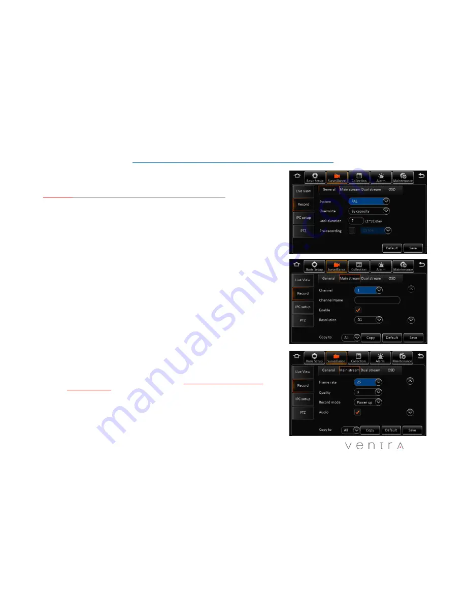
4.3 Surveillance – Record  - General

Reminder: 

Save each tab individually before proceeding to next tab

This section covers the general system wide setting of the XDR

1.

System –

PAL / NTSC   (Default = NTSC)

2.

Overwrite

: How the system stores new recording once the storage is full

-

Capacity

:  As SD storage is full, system will overwrite oldest data

-

Date

:  XDR will overwrite old data based on date

-

Alarm

:  XDR will overwrite old data based on alarm

4.

Lock Duration

:  Number of days to lock an alarm event file 1 – 31 days (Default 7 days)

5.

Pre-Recording

:  Enable/ Disable and Length of recording before an event                                                        

(Recommend  1 to 3 minutes)

4.4   Surveillance – Record – Main Stream

This section enables, disables individual cameras as well as custom parameters for each.  If setting 
is same for all cameras, click “Copy To > All”. 

1.

Channel:  

Select the camera from Channel 1 - 12

2.

Channel Name:  

Assign name to each channel - optional ( rear, side door, interior…etc)

3.

Enable:  

Enable or Disable each camera in the system. If camera is NOT enabled, it will NOT 

record in the system

4.

Resolution

:  Select resolution for camera  

Analog HD (AHD) Camera 

=  CH 1 ~ 8  =   1080P AHD, 720P AHD,  D1

IPC HD Camera 

=  CH 9 – 12   =  1080P HD, 720P HD Resolution 

5.

Frame Rate:  

Select frame rate of individual camera (1 – 30FPS)  Default 25

Higher the frame rate, bigger the file storage size

Summary of Contents for XDR-1280/D

Page 1: ... use Save for future reference Specification models and features are subject to change without prior notice www ventrainc com Manual Ver 08 18 This manual covers the setup connection and features of the XDR For management software refer to Ventra software manual THIS MANUAL CONTAINS UPDATED FEATURES AND SPECIFICATION PLEASE REFER TO UPDATE NOTICE ...

Page 2: ...8 EX4 XC4 SERIES AHD CAMERAS 16 EX12 ALC ALARM CABLE 17 CONNECTION POWERING THE XDR 1280 CONNECTING POWER CABLE FUSE 18 CONNECT EX4 XC SERIES AHD CAMERAS EX12 CAM8 19 CONNECT XDR PON 4 PORT SWITCH TO XDR 1280 20 CONNECT XDR PON 4 PORT SWITCH FOR EX5 HD CAMERAS 21 VIDEO OUT CONNECTION TO LCD MONITOR 22 XDR SYSTEM SETUP VIA EX4 PGM 23 SECTION 1 SYSTEM SETUP FORMAT SD CARD OSD MENU SCREEN 24 1 1 1 2 ...

Page 3: ...SPLAY 34 4 6 4 7 SURVEILLANCE EX5 HD IPC CAMERA SETUP 35 4 9 SURVEILLANCE PTZ CAMERA SETUP 36 SECTION 5 COLLECTION OF DATA COD SENSOR SETTING 5 0 5 2 COD SENSOR GENERAL SENSOR SERIAL SPEED 37 5 3 5 4 COD SENSOR IMAGE SNAPSHOT TIME TRIGGER SETTING 38 SECTION 6 ALARM SETTING 6 0 ALARM OVERSPEED 39 6 1 ALARM PANIC ALARM 40 6 2 ALARM INPUT ALARM 41 6 3 ALARM VIDEO LOSS 42 6 4 ALARM ADVANCE 43 SECTION ...

Page 4: ...e Alarm sensor trigger speed acceleration video loss temperature Pre Recording Post recording Pre Recording 0 60 Minutes Post Recording 0 30 Minutes Mirror Recording Support Playback Backup Playback Channel 1 channel by local playback Search Mode Date time channel file type GPS GPS route history speed detection and time sync Storage HDD SATA SSD Max 1TB 2 5 SATA 5400RPM HDD 1TB SSD Interface USB U...

Page 5: ...lity Level 1 8 1 2 3 4 5 6 7 8 CIF 352 x 240 Stream kB s 1024 768 640 512 440 350 312 280 MB Hour CH 450 338 281 225 193 154 137 123 D1 VGA 704 X 480 Stream kB s 2048 1536 1280 1024 900 800 720 640 MB Hour CH 900 675 563 450 396 352 316 281 720P 1280 x 720 Stream kB s 6144 4800 4128 3456 2784 2112 1440 768 MB Hour CH 2700 2109 1814 1519 1223 928 633 338 1080P 1920 x 1080 Stream kB s 8192 6390 5505...

Page 6: ...ed or damaged When exposed to direct sunlight for a period of time the equipment may become hot Please exercise caution when touching the equipment Do not disassemble or alter the equipment cable or accessories as this may lead to equipment error and failure thus voiding all warranty In the event of an impact or accident please check to ensure the equipment is properly secured Inspect the mounting...

Page 7: ...hibit recording of audio and or video in vehicles or public area or without knowledge and or consent please check and comply with ALL local state and federal laws and regulations Certain local state and federal laws may require signage or display that indicate recording of audio and or video in vehicles or public area Please check and comply with ALL local state and federal laws and regulations IT...

Page 8: ...DD or SD card error and or damage computer issues or virus XDR utilizes a propriety file format for security each HDD SD card MUST be formatted IN the XDR prior to use 8 IMPORTANT HDD and SD Card Requirement and Compatibility It is extremely important to use HDD and SD cards that are suitable for rugged environments constant data writing continuous operation and models that are designed specifical...

Page 9: ...connection 1 2 3 Labeling may differ due to product update 5 4 6 1 Removable Hard Drive Cradle HDD provides the main storage for recorded data Supports up to 2TB HDD Never remove or insert HDD while XDR is on 2 Mirror SD Card Slot SD card provides mirror recording of events Never remove or insert HDD while XDR is on 3 Status LED Provides visual system operation status 4 USB Port For USB flash driv...

Page 10: ...nnection cable harness 1 Power Connection Main power connection to vehicle fuse or XDR PON network switch 9 36V DC 2 Amplifier Connection to external microphone and accessories in development 3 Panel Connection to EX4 PGM touchscreen tablet 4 LAN Port Connection for external WiFi or Cellular router as well as XDR PON EX5 HD series IP camera switch 5 USB Port Connection for external USB devices 6 S...

Page 11: ...System Dimension 11 ...

Page 12: ...Hard Drive Installation 12 Note Hard drive already pre installed in each XDR ...

Page 13: ...omponents 13 Included Optional EX5 HD3IP1080 EX5 HD2 720P HD Camera w IR Audio EX4 XC2 Analog D1 Outdoor Camera EX4 XC4 Left Right Side Outdoor D1 Analog Camera EX4 PGM Tablet for Programming Back Up Monitor XDR PON 4 Port Switch required for EX5 HD series cameras EX5 CBLxx HD Camera Patch Cable 15ft 30ft and 50ft EX4 CBLxx 4 pin DIN Camera Patch Cable 15ft 60ft EX12 ALC Input Output Alarm Cable ...

Page 14: ...1 Connect to EX4 PON Switch External Cellular WiFi router Passive GPS VLCD 7 LCD monitor 14 To Vehicle Power Source 3 Wires 12 24V DC Red GND BLK ACC IGN YEL Inline Fuse Must be connected to XDR power cable for system to power on 12V Blue Fuse 24V Red Fuse EX4 PGM ...

Page 15: ...XDR System Layout Diagram 15 3 Wires 12 24V DC Red GND BLK ACC IGN YEL ...

Page 16: ...r 8 AHD cameras and 1 video output to monitor Up to 8 AHD cameras AV IN 1 AV IN 8 1080P AHD 720P HD D1 Resolution 4 pin DIN connection 1 DIN female video out connection AV OUT 1 Must connect to EX12 MPIG to convert to BNC connection 16 ...

Page 17: ...t Triggered Voltage 12V Default Voltage 0V EX12 ALC Input Output Trigger Cable Guide Trigger Cable Can Be connected for a wide array of applications Door Open Close Contact Light Trigger Siren Trigger Reverse Gear Signal PTO Trigger Lift Arm Gate PTZ controller 17 ...

Page 18: ...onnection on the XDR XDR Cover Latch MUST BE CLOSED in order for the XDR to Power ON Fig 2 Fuse Blade Fig 1 Pic of Power Cable Fig 3 XDR Power connection CAUTION Installation by a Professional technician is highly recommended Exercise caution when connecting the power to prevent shock Do not use sharp object to force cable Ensure connection to the proper fuse to avoid damage or interference with v...

Page 19: ...ector at the rear of the XDR shown in Figure 1 Each EX4 XC4 series camera that connects to the XDR requires an EX4 CBLxx cable to XDR Figure 2 EX4 CBLxx xx denotes length XDR transmits Audio Video Power through the 4 PIN DIN cable Figure 3 EX4 CBL available in 15 33 and 60ft Maximum length distance is 120ft by connecting 2 EX4 CBL4 Figure 3 EX12 CAM8 Figure 1 Figure 2 EX4 CBL ...

Page 20: ...IN cable and XDR PON 4 camera switch sold separately Connect the power cable included with the XDR PON to both the XDR 1280 and the PON switch Switch wire connects to XDR PON Output wire connects to XDR 1280 Input wire connects to power cable of the XDR Fig 2 Connect Power to XDR and XDR PON Fig 1 XDR PON Switch ...

Page 21: ... XDR PON 4 camera switch sold separately Connect an Ethernet CAT5 cable from the LAN port on the rear of XDR 1280 to the PON switch port labeled MDVR Connect EX5 CBLxx 6 PIN DIN cable to IPC port 1 4 sold separately EX5 CBLxx xx denotes length available in 15 30 and 50ft Fig 2 Connect Power to XDR and XDR PON IPC port for HD camera Fig 1 XDR PON Switch ...

Page 22: ...CD Screen Connection 1 Connect EX12 CAM8 to XDR 3 Use a BNC to VGA Converter to connect to the Video Cable Lead on EX12 MPIG 22 2 Using AV Out 1 port to connect to EX12 MPIG included with XDR 4 Connect RCA cable to EX12 MPIG ...

Page 23: ...uch Screen Programming Tablet and LCD monitor EX4 PGM Programming XDR system LCD monitor for live viewing back up Touch Screen for easy access 23 Connect the EX4 PGM with the 5M extension cable to the Panel Connector on XDR ...

Page 24: ...24 OSD Menu Layout Live View Display Screen Mode Playback System Status Setting ...

Page 25: ...D SD card while XDR is powered ON 4 To connect to the XDR there are 2 methods Mouse to the USB port on the XDR EX4 PGM programming tablet 5 To Format the card Login to XDR Settings by selecting the Login Setup Maintenance Storage Default ID admin Password admin 6 Select Maintenance Tab Storage Tab pick the SD Slot to format Any previous data will be erased 7 Top Slot Primary Bottom Slot Secondary ...

Page 26: ...vice Info Reminder Save each tab individually before proceeding to next tab 1 Device ID currently not in use 2 Vehicle Info Vehicle Number Required for software to identify system Vehicle Plate Optional Line Number Optional 3 Driver Info Driver Number Optional Driver Name Optional ...

Page 27: ...l GPS receiver Once signal is acquired XDR will automatically sync time 5 Center Server synchronize time with time server optional 6 NTP Sync Syncs to specified time servers Optional Multiple sync methods can be selected XDR will select the signal based on availability 2 2 Daylight Saving Time DST 1 Enable Disable DST 2 Select Hour Offset from dropdown menu 3 Select Mode from drop down menu 4 Ente...

Page 28: ... will power on from either trigger However both criteria have to be met in order for the XDR to power off XDR will not shut off if the scheduled shut down time has been reached while the vehicle ignition is still on 2 4 Startup Low Battery 1 Sleep No consumption standby 2 Low Voltage Protect Enable Disable the XDR from auto shutting off when reaching the low battery voltage threshold to prevent ba...

Page 29: ...e logging out Recommend 10 Minutes 2 User Name Default are admin and user 3 User Group It is categorized as Administrator and Normal user Admin View videos change settings and export logs User View videos but cannot change settings or logs Add Delete or Edit 1 Only Administrators can delete or add new users up to 2 2 User name cannot be duplicated or empty 3 Edit Change password ...

Page 30: ...et cable and optional XDR remote viewing monthly service sold separately This enables the XDR 1280 D to connect to an external WiFi and or Cellular Router via Ethernet connection Additional settings are required in the Network Tab within the XDR For detailed info refer to XDR Remote Connectivity User Guide ...

Page 31: ... select 1 4CH Must Select 4 4 1 Surveillance Live View Auto Loop 1 Auto loop allows different cameras to be displayed on a monitor with its unique time duration 2 Add Edit Or Delete Cameras and settings 3 Add Enable Auto Loop box to access Add Screen Button select desired camera and duration of display 4 Delete Click the X Button of the camera to be deleted 5 Edit Click the Menu button icon of the...

Page 32: ...ording Enable Disable and Length of recording before an event Recommend 1 to 3 minutes 4 4 Surveillance Record Main Stream This section enables disables individual cameras as well as custom parameters for each If setting is same for all cameras click Copy To All 1 Channel Select the camera from Channel 1 12 2 Channel Name Assign name to each channel optional rear side door interior etc 3 Enable En...

Page 33: ...audio recording if camera supports audio 8 Alarm Quality XDR supports separate video recording quality in terms of bit stream between Normal and Alarm Default Video quality is 3 and Alarm Quality is 2 For example Normal recording can be changed to 4 to reduce storage size and Alarm Quality at 2 so when an event occurs video quality is enhanced 9 Encode Mode VBR CBR Default VBR VBR Variable Bit Rat...

Page 34: ...t Internal SD 2 Record Mode Mirror Alarm Back Up Sub Stream None Select None Mirror Mirroring identical data to be stored on both SD cards Channel selectable Alarm Backup Events triggered by Alarm are stored Substream Substream is a sub recording of the Main recording that can be compressed in video quality and resolution Individual parameters can be set based on selected cameras None Continuous L...

Page 35: ...ble EX5 HD camera scroll down to CH 9 12 to Enable the appropriate camera 3 Click on Magnifying glass on the selected CH for XDR to scan and auto detect IP address once camera is connected 4 To view change or manually enter IP address of each camera user can also select the menu option 5 Outside This setting optimizes the EX5 HD camera when installed in outdoor environment If system does not detec...

Page 36: ... for PTZ enabled analog or IP cameras Setup 1 Enable Disable PTZ function in each Channel 2 Operate Serial N9M ONVIF 3 Protocol Type Serial Mode Supports N9M Onvif Pelco D Pelco P PTZ 4 Address Applies to Serial mode 5 Test Test PTZ function select Test to enable On Screen PTZ control panel ...

Page 37: ...3 OSD Name The name embedded in video and data recordings 4 Copy If settings are the same select Copy To individual or all sensors 5 1 Collection General Serial Port 1 RS232 1 RS232 2 Applies to 3 Axis G Sensor Expansion 485 Bus signal and GPS data 2 RS485 1 RS485 2 Applies to PTZ control panel 485 Bus signal and GPS Data 3 Baud Rate 2400 115 200 9 classes optional 5 2 Collection General Speed 1 U...

Page 38: ...supports up to 8 different schedules for image Snapshot configuration 5 4 Collection Snap Setting Trigger Snap 1 Alarm Snap Snap Link Setup Select camera channel Enable disable image snapshot feature Select resolution of image D1 WD1 CIF Select image quality 1 8 1 Best Upload Type Available only in XDR 480 and XDR580 Snap number of images Interval 5 3600 seconds Click Ok to Save or Copy to apply s...

Page 39: ...n specific alarm is triggered Post Recording Duration of recording to be marked as post alarm event Lock Lock specific alarm recording to keep for specified duration refer to section 4 3 General Surveillance Record Lock Duration days 1 31 days 3G Applicable only for the XDR 580H Linkage Output 1 or 2 Enable link alarm output when alarm is triggered Output delay Time alarm output duration after ala...

Page 40: ...t Lock Lock specific alarm recording to keep for specified duration refer to section 4 3 General Surveillance Record Lock Duration days 1 31 days 3G Applicable only for the XDR 580H Linkage Output 1 or 2 Enable link alarm output when alarm is triggered Output delay Time alarm output duration after alarm is removed 0 255 secs Alarm upload Enable to upload to platform Only on XDR 580 Linkage screen ...

Page 41: ...uration of recording to be marked as post alarm event Lock Lock specific alarm recording to keep for specified duration refer to section 4 3 General Surveillance Record Lock Duration days 1 31 days 3G Applicable only for the XDR 580H Linkage Output 1 or 2 Enable link alarm output when alarm is triggered Output delay Time alarm output duration after alarm is removed 0 255 secs Alarm upload Enable t...

Page 42: ...rked as post alarm event Lock Lock specific alarm recording to keep for specified duration refer to section 4 3 General Surveillance Record Lock Duration days 1 31 days 3G Applicable only for the XDR 580H Linkage Output 1 or 2 Enable link alarm output when alarm is triggered Output delay Time alarm output duration after alarm is removed 0 255 secs Alarm upload Enable to upload to platform Only on ...

Page 43: ...Alarm Base Configuration 43 6 4 Alarm Advanced G Sensor Alarm Feature Currently Not Available ...

Page 44: ...ation Insert USB Thumb drive to export the configuration file to the root folder file name is ConfigFile Insert flash drive to import configuration file into XDR System will display notice when import successfully completed Remark Config file does not import the register info and speed adaption info 7 1 Maintenance File Data Export Setup XDR supports exporting of data to USB thumb drive for specif...

Page 45: ... Upgrade menu user can update Firmware for XDR EX5 HD camera IPC or EX4 PGM CP4 programming tablet Download and Copy firmware to a BLANK USB thumb drive Firmware must be saved into a folder labeled upgrade on the USB drive Insert USB Thumb drive to USB port and select specific Upgrade System will reboot and display notice when import successfully completed For latest firmware visit www ventrainc c...

Page 46: ...ting for file export import Storage type Refer to HDD SD card requirement and specification on PAGE 7 HDD Internal 1TB Max SD card Internal Max 128GB per slot U1 speed minimum USB drive for File Export Settings Import Export Firmware updates Insert HDD and or SD card if applicable while system is powered off Select Format for storage device Once format is completed capacity of each device will be ...

Page 47: ...d The Customer will be solely responsible for shipping charges insurance and proper packaging to prevent breakage in transit whether or not the product is covered by this warranty All shipments of repaired or replaced products by Ventra will be F O B California VENTRA MAKES NO OTHER WARRANTIES EXPRESS OR IMPLIED AS TO MERCHANTABILITY OR FITNESS FOR A PARTICULAR PURPOSE OF ANY PRODUCT SOLD UNDER TH...

Page 48: ...1578 W San Bernardino Rd E Covina CA 91722 USA www ventrainc com info ventrainc com Tel 888 418 3833 Innovative solutions in vehicle and mobile video technology ...

Reviews: