


3.
Loosen the screw at the bottom of the grille, and then remove the grille by
carefully pulling away from the housing.
4.
Mark the screw centres through the holes in the fan back plate. Drill, plug
and screw into position.
5.
Wire the fan as described in Section B-Wiring. Adjust any settings as
required (see Section C-Setup).
6.
After installation, ensure impeller rotates freely.
7.
Replace the grille and tighten the retaining screw.
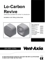
WINDOW MOUNTING
For window mounting refer to the instructions provided with the kit.
B. WIRING.
WARNING: THE FAN AND ANCILLARY CONTROL EQUIPMENT
MUST BE ISOLATED FROM THE POWER SUPPLY DURING
INSTALLATION OR MAINTENANCE.
IMPORTANT
The cross - sectional area of supply cord used should be ranged from 1 -1.5mm
2
.
The extraction fan or transformer (SELV models) is suitable for connection to
220-240V 50Hz supply.
The
Transformer (SELV models only)
MUST
be surface mounted to allow air
to freely circulate around the unit. When installed in a loft void it
MUST
NOT
be
enclosed or covered with insulation.
The fan is a class ll double insulated product and
MUST NOT
be earthed.
1.
Select and follow the appropriate wiring diagram. (Fig. 1, 2, 3, OR 4, 5, 6)
2.
Check all connections have been made correctly and ensure all terminal
connections and supply wires are securely fastened.
3.
Ensure the impeller rotates and is free from obstructions.
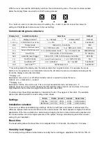
C. SETUP
Accessing the commissioning menu
To configure the fan first remove the grille. With the grille removed the control board is
visible (Fig.7). Do NOT isolate the fan from the power
supply as configuration requires power to the fan;
removing the grille will automatically stop the impeller
from spinning
.
Once the fan has been commissioned please write the
installation date in the box on the label provided.
IMPORTANT
Do NOT
attempt to remove the circuit board cover (Fig.7). This
covers the high voltage power supply, preventing the risk of an
electric shock.