


Page 8 of 12
8.
The Mains cable gland must be then tightened and secured.
9.
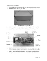
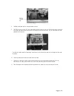
The 2 Molex connectors from the Fan unit must then be pushed through the hole in the Controller housing and connected
to the appropriate Molex connectors inside the PCB (fitting red to red and blue to blue). They are colour coded as well as
polarised to aid connection.
The motor connections should be fitted through the cable entry on the left, while the cable entry on the right should be used
for switches.
10. The cable gland around this cable must also be securely fitted.
11. The sensor or switch used with the product should be connected via the remaining cable gland using a 10-12mm
diameter cable. The blind grommet should only be used if the other cable gland routes are already used
12. Once all wiring has been completed and the cable glands secured, replace the cover by replacing the 6 screws.
Earthing
Crimped
Eye