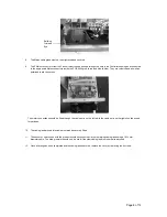
Vent-Axia INTEGRA PLUS Installation And Wiring Instructions Download Page 12


Page 12 of 12


Head Office: Fleming Way, Crawley, West Sussex, RH10 9YX. 
 

UK NATIONAL CALL CENTRE

, Newton Road, Crawley, West Sussex, RH10 9JA


SALES ENQUIRIES: 


Tel: 0844 8560590  

Fax: 01293 565169


TECHNICAL SUPPORT: 

Tel: 0844 8560594  

Fax: 01293 532814 


For details of the warranty and returns procedure please refer to www.vent-axia.com or write to Vent-Axia Ltd, Fleming Way, Crawley, RH10 9YX


438178C  


1212 


The


Guarantee 

Applicable only to products installed and used in the United Kingdom.  For details of guarantee outside the United Kingdom contact 
your local supplier. 
Vent-Axia guarantees its products for two years from date of purchase against faulty material or workmanship.  In the event of any 
part being found to be defective, the product will be repaired, or at the Company’s option replaced, without charge, provided that 
the product:- 


Has been installed and used in accordance with the instructions given with each unit. 


Has not been connected to an unsuitable electricity supply. (The correct electricity supply voltage is shown on the 
product rating label attached to the unit). 


Has not been subjected to misuse, neglect or damage. 


Has not been modified or repaired by any person not authorised by the company. 

IF CLAIMING UNDER TERMS OF GUARANTEE 

Please return the complete product, carriage paid to your original supplier or nearest Vent-Axia Centre, by post or personal visit.  

Please ensure that it is adequately packed and accompanied by a letter clearly marked “Guarantee Claim” stating the nature of the 

fault and providing evidence of date and source of purchase. 


The guarantee is offered to you as an extra benefit, and does not effect your legal rights 

Summary of Contents for INTEGRA PLUS

Page 1: ...INTEGRA PLUS Installation and Wiring Instructions 230V 50Hz PLEASE READ INSTRUCTIONS IN CONJUNCTION WITH ILLUSTRATIONS PLEASE SAVE THESE INSTRUCTIONS IPX2 Stock Ref N INTEGRA PLUS 437666...

Page 2: ...NFORMING TO BS5733 OR BS1363 PART 4 A 3 AMP BS1362 FUSE SHOULD BE FITTED TO THE CONNECTION UNIT WHICH MUST BE LOCATED OUTSIDE OF A ROOM CONTAINING A FIXED BATH OR SHOWER 4 WARNING THIS APPLIANCE IS CL...

Page 3: ...Page 3 of 12 Cover Heat Recovery Cell Supply Motor Base Extract Motor Controller Air Direction Exploded View of Fan unit Supply to Rooms Extract from Rooms Intake from Outside Exhaust to Outside...

Page 4: ...here are two forms of installation for the INTEGRA PLUS To mount the unit on joists Place the unit across two beams and attach the appropriate cabling drainage and ductwork to the unit with the Vent A...

Page 5: ...DS THE CONDENSATE DRAIN Fig 3a Mounted on joists Fig 3b Ceiling mounted 8 CORE CONTROLLER CABLE 8 CORE CONTROLLER CABLE Fig 4 Water trap details WATER TRAP CONDENSATION DRAIN FROM UNIT SILICON SEALER...

Page 6: ...suitable installation site allow for an extra 30mm clearance either end for cable glands Note that the unit can be ceiling or floor mounted The site selected must allow sufficient space around the uni...

Page 7: ...he appropriate terminals 5 Ensure the wires are securely fixed into the terminal block after use 6 A 10 12mm outside diameter 3 core mains lead should enter the controller hosing via the cable gland n...

Page 8: ...otor connections should be fitted through the cable entry on the left while the cable entry on the right should be used for switches 10 The cable gland around this cable must also be securely fitted 1...

Page 9: ...Wiring via 3 Ambient Response Humidity Sensors Normal Purge Fig 4 Wiring via an Ambient Response Humidity Sensor Timeswitch Boost Relay Com NC NO Fuse L N E 1 Phase supply 220 240V 50 Hz Switched fuse...

Page 10: ...m available Chlorine solution Cleaning Procedure 1 Heat Recovery Cell Remove from appliance and wash ensuring that the sterilising solution penetrates between the Cell plates All parts should be well...

Page 11: ...e end user Appendix 1 Air Performance Graph HR300XL Air Performance Extract Supply 0 100 200 300 400 500 600 0 100 200 300 400 500 600 Volume Pressure Pa m h l s 0 25 50 75 100 125 150 50V 62V 74V 86V...

Page 12: ...product will be repaired or at the Company s option replaced without charge provided that the product Has been installed and used in accordance with the instructions given with each unit Has not been...

Reviews: