


Page 4 of 12
Installers Guide
This Appliance must be sited and connected in accordance with current UK Building, Factory and IEE wiring regulations
(BS7671) or the appropriate national regulations in your country and carried out by a suitably qualified person.
The size of the fan unit and the controller and space for access to screws or other fixings must be considered when choosing a
suitable location for installation.
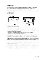
A) Installing the Fan unit
Fig 1 – The size of the unit
All dimensions are in mm unless otherwise stated.
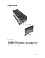
1. Remove the ventilation unit from the packaging.
2. After noting the positions of the duct spigots, cable and drainage connection on the ventilation unit, select a suitable
installation site and type (see below). Note that the unit must be mounted with the drainage at the bottom (3 or 5-degree tilt
towards the drain). The site selected must allow sufficient space around the unit for the removal of the ducts, cover and heat
exchanger for maintenance and servicing purposes.
3. If appropriate, provide mains electrical supply and drainage system in the vicinity of the installation site.
4. Typically there are two forms of installation for the INTEGRA PLUS
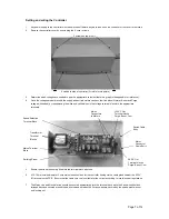
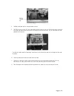
To mount the unit on joists:
Place the unit across two beams and attach the appropriate cabling, drainage and ductwork to
the unit, with the Vent-Axia bubble badge facing up. For optimum performance, ensure the ductwork does not turn 90deg
directly off the spigots. The unit should, for optimum drainage, be tilted by 3 degrees towards the drain side. See Fig. 3a.
Ceiling mounted:
. Invert the unit with the Vent-Axia logo facing down and attach the unit securely to the rafters. For optimum
performance, ensure the ductwork does not turn 90deg directly off the spigots. The unit should, for optimum drainage, be tilted
by 3 degrees towards the drain side. See Fig. 3b.
Please note - the situation and type of installation for the unit must be decided and assembled before any drainage knockouts
are removed, as they cannot be refitted.
5.
Having decided upon a location and position remove the knock out for the condensate drain, this must be at the lowest
point. Connect the drain of the ventilation unit to the drainage system using suitable ‘U’-bends (see fig 4).
6.
Install suitable internal and external grilles/ terminals and connect them to the ventilation unit using suitable 150mm
ducting. If flexible ducting is used, it should be stretched in order to obtain the best performance.