16
To replace parts such as nozzle supports, valves and electric components follow the procedure described in the burner
adjustment paragraph. To replace the valve or the gas thermostat, it is also necessary to disassemble the two rear gas
train brackets, loosening the 4 screws (2 per bracket) that attach it to the rest of the cooker and, unscrew the nuts that
attach the front burner valves to the control support, after removing all the knobs. To replace the gas or electric
thermostat, also disassemble the rear cooker guard, loosening the relative screws, to be able to pull out and reposition
the thermostat bulb.
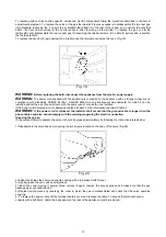
To replace the oven bulb, just unscrew the protection cap that projects out inside the oven. (Fig.19)
Fig. 19
WARNING:
Before replacing the bulb, disconnect the appliance from the electric power supply.
WARNING:
The power cord supplied with the appliance is connected to the appliance with an
X
type connection (in
compliance with standards AS/NZS 60335-1, AS/NZS 60335-2-6 and subsequent amendments) for which it can be
installed without the use of special tools, with the same type of cord as the one installed.
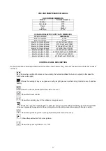
If the power cord becomes worn or damaged, replace it based on the information reported in table 4.
WARNING:
If the power cord is replaced, the installer shall ensure that the ground cable is longer than the
phase cables and also should comply with the warnings regarding the electric connection.
Greasing the valves:
If it becomes difficult to operate the valve, it should be greased immediately by following the instructions listed below:
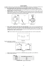
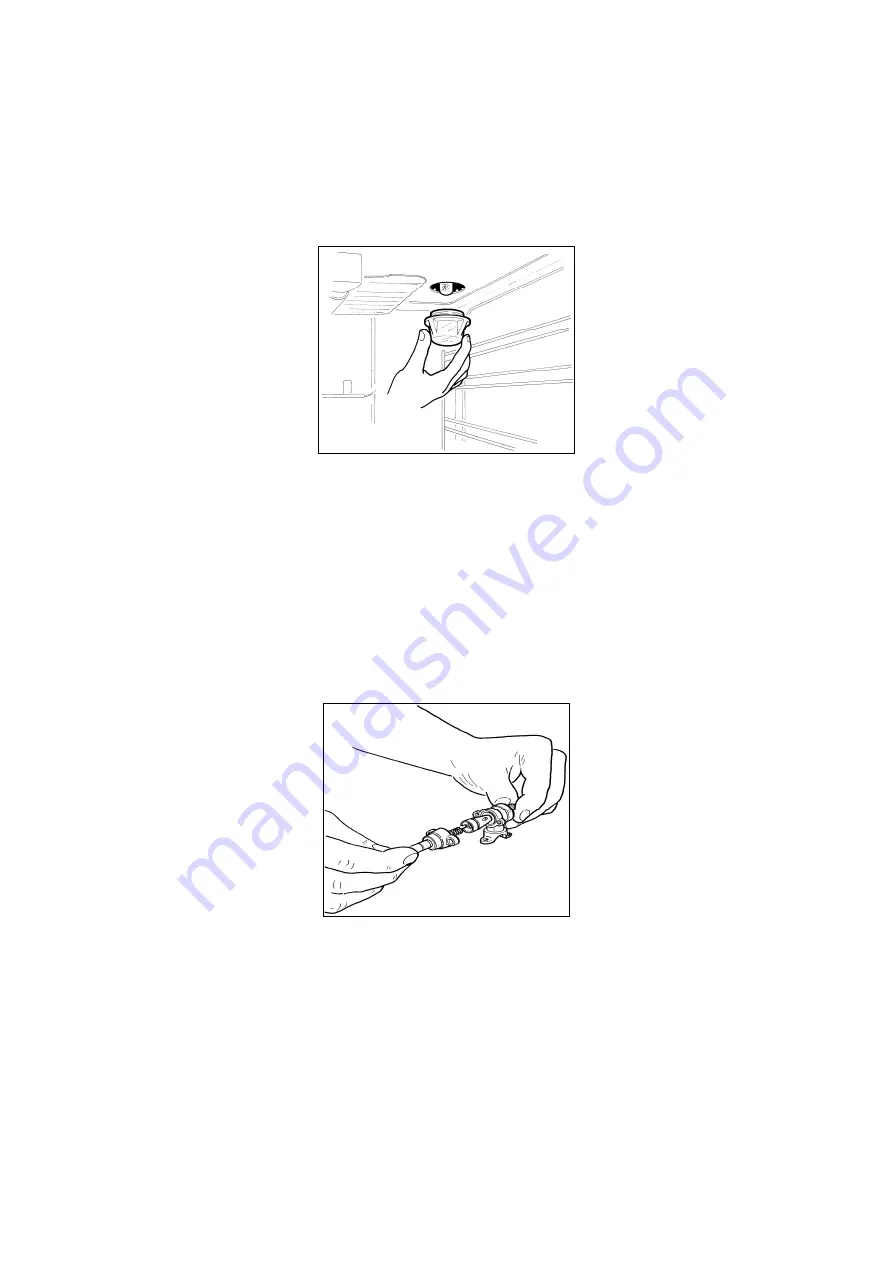
1) Disassemble the valve body by loosening the two screws located on the body of the valve (Fig.20)
Fig. 20
2) Extract and clean the seal cone and its housing with a rag soaked with thinner.
3) Lightly grease the cone with special grease.
4) Insert the cone, moving it several times, remove it again, remove the excess grease and make sure that the gas
passage ways are unobstructed.
5) Replace all the pieces by reversing the order in which they were disassembled and check that the valve operates
correctly.
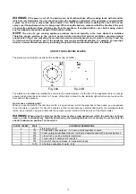
6) To replace the power cable, lift the terminal board’s cover and replace the cable. To access the terminal board in
cookers with a 3x2.5mm² cable, the back panel on the rear of the appliance must be removed.


