background image

38

9 Supplement

VEGASWING 63 • Two-wire 8/16 mA

29232-EN-180704

Influence of the process pressure to the switching point

1

2

3

4

  12 

(174,1)

 38 

(551,1)

  25 

(362,6)

  51 

(739,7)

 64 

(928,2)

10 

25

/

64

")

  8 

5

/

16

")

  6 

15

/

64

")

  4 

5

/

32

")

  2 

5

/

64

")

-2 

(

-5

/

64

")

-4 

(

-5

/

32

")

-6 

(

-15

/

64

")

-8 

(

-5

/

16

")

-10 

(

-25

/

64

")

0

Fig. 43: Influence of the process pressure to the switching point
1  Shifting of the switching point in mm (in)

2  Process pressure in bar (psig)

3  Switching point at reference conditions (notch)

4  Tuning fork

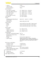
Repeatability

0.1 mm (0.004 in)

Hysteresis

approx. 2 mm (0.08 in) with vertical installation

Switching delay

approx. 500 ms (on/off)

Measuring frequency

approx. 1200 Hz

Ambient conditions

Ambient temperature on the housing

-40 … +70 °C (-40 … +158 °F)

Storage and transport temperature

-40 … +80 °C (-40 … +176 °F)

Process conditions

Measured variable

Limit level of liquids

Process pressure

-1 … 64 bar/-100 … 6400 kPa (-14.5 … 928 psig)
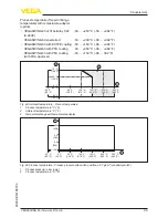
The process pressure is dependent on the process 

fitting, for example Clam p or flange (see the following 

diagrams)

Maximum allowable operating pressure 100 bar/10000 kPa (1450 psig) or 1.5 times process 

pressure
The function of the instrument is ensured up to an 

operating pressure of 100 bar/10000 kPa (1450 psig) at 

a maximum process temperature of +50 °C (+122 °F) 

(only with threaded versions).

Process temperature (thread or flange 

temperature)


Ʋ VEGASWING 63 of 316L/Alloy C22 

(2.4602)

-50 … +150 °C (-58 … +302 °F)

Summary of Contents for VEGASWING 63

Page 1: ...Operating Instructions Vibrating level switch with tube extension for liquids VEGASWING 63 Two wire 8 16 mA Document ID 29232 ...

Page 2: ...7 3 2 Principle of operation 8 3 3 Adjustment 8 3 4 Storage and transport 9 3 5 Accessories 9 4 Mounting 11 4 1 General instructions 11 4 2 Mounting instructions 15 5 Connecting to power supply 18 5 1 Preparing the connection 18 5 2 Connection procedure 18 5 3 Wiring plan single chamber housing 19 5 4 Wiring plan version IP 66 IP 68 1 bar 21 6 Setup 22 6 1 General information 22 6 2 Adjustment ele...

Page 3: ...ights 45 9 4 Trademark 45 Safety instructions for Ex areas Take note of the Ex specific safety instructions for Ex applications These instructions are attached as documents to each instrument with Ex approval and are part of the operating instructions manual Editing status 2018 06 23 ...

Page 4: ...ntering the Document ID on www vega com you will reach the document download Information tip note This symbol indicates helpful additional information Caution If this warning is ignored faults or malfunctions can result Warning If this warning is ignored injury to persons and or serious damage to the instrument can result Danger If this warning is ignored serious injury to persons and or destructi...

Page 5: ... mounting or adjustment Thus dam age to property to persons or environmental contamination can be caused Also the protective characteristics of the instrument can be influenced 2 4 General safety instructions This is a state of the art instrument complying with all prevailing regulations and directives The instrument must only be operated in a technically flawless and reliable condition The operat...

Page 6: ...allation and operation in the USA and Canada This information is only valid for USA and Canada Hence the follow ing text is only available in the English language Installations in the US shall comply with the relevant requirements of the National Electrical Code ANSI NFPA 70 Installations in Canada shall comply with the relevant requirements of the Canadian Electrical Code 2 9 Safety instructions ...

Page 7: ...onal Ex specific Safety instructions with Ex versions If necessary further certificates The VEGASWING 63 consists of the components Housing lid Housing with electronics Process fitting with tuning fork 1 2 3 Fig 1 VEGASWING 63 1 Housing lid 2 Housing with electronics 3 Process fitting The type label contains the most important data for identification and use of the instrument Article number Serial...

Page 8: ...ion Line break to the piezo drive If one of these faults is detected the electronics signals it via a defined current to the signal conditioning instrument The connection cable to the sensor is also monitored for line break and short circuit The tuning fork is piezoelectrically energised and vibrates at its mechanical resonance frequency of approx 1200 Hz The piezos are fixed mechanically and are ...

Page 9: ...eceipt Ascertained transit damage or con cealed defects must be appropriately dealt with Up to the time of installation the packages must be left closed and stored according to the orientation and storage markings on the outside Unless otherwise indicated the packages must be stored only under the following conditions Not in the open Dry and dust free Not exposed to corrosive media Protected again...

Page 10: ...SG63 3 up to 64 bar The wetted parts of the lock fitting can be either of steel 316L or Alloy C22 2 4602 Lock fittings cannot be used in coated tube extensions You can find additional information in the operating instructions manu als of the lock fittings For connecting the sensors with a separator to voltage supply or sig nal processing the sensors are also available with plug connectors The foll...

Page 11: ...g fork is at the height of the desired switching point The tuning fork has lateral markings notches that indicate the switching point with vertical mounting The switching point applies to water in conjunction with the basic setting of the density switch 0 7 g cm 0 025 lbs in When mounting VEGASWING 63 make sure that this marking is at the height of the requested switching point Keep in mind that t...

Page 12: ...ing point with higher density 4 Switching point approx 27 mm 1 06 in 1 2 Fig 3 Horizontal mounting 1 Switching point 2 Marking with screwed version facing up 1 2 Fig 4 Horizontal installation recommended mounting position particularly for adhesive products 1 Switching point 2 Marking with screwed version facing up In the case of flange versions the fork is aligned as follows ...

Page 13: ...n cable downward in front of the cable entry Rain and condensation water can thus drain off This ap plies mainly to outdoor mounting as well as installation in areas where high humidity is expected e g through cleaning processes or on cooled or heated vessels To maintain the housing protection make sure that the housing lid is closed during operation and locked if necessary Make sure that the degr...

Page 14: ...switch is a measuring instrument and must be treated accordingly Bending the vibrating element will destroy the instrument Warning The housing must not be used to screw the instrument in Applying tightening force can damage internal parts of the housing Use the hexagon above the thread for screwing in Metric threads In the case of instrument housings with metric thread the cable glands are screwed...

Page 15: ... Marking In case of horizontal mounting in adhesive and viscous products the surfaces of the tuning fork should be vertical in order to reduce buildup on the tuning fork On the screwed version you will find a marking on the hexagon With this you can check the position of the tuning fork when screwing it in When the hexagon touches the seal the thread can still be turned by approx half a turn This ...

Page 16: ...zontal position Extreme vibration caused by the process or the equipment e g agitators or turbulence in the vessel can cause the extension tube of VEGASWING 63 to vibrate in resonance This leads to increased stress on the upper weld joint Should a longer tube version be neces sary you can provide a suitable support directly above the tuning fork to secure the extension tube This measure applies ma...

Page 17: ... gas tight leadthrough option prevents an uncontrolled leakage of the medium The service life of the gas tight leadthrough depends on the chemical resistance of the materials See Technical data Caution If it is determined e g via an error message from VEGASWING 63 that medium has already penetrated into the vibrating element the instrument must be exchanged immediately Gas tight leadthrough ...

Page 18: ...zardous areas must be given priority The data for power supply are specified in chapter Technical data The instrument is connected with standard two wire cable without screen If electromagnetic interference is expected which is above the test values of EN 61326 for industrial areas screened cable should be used Make sure that the cable used has the required temperature resist ance and fire safety ...

Page 19: ...screwdriver 8 Check the hold of the wires in the terminals by lightly pulling on them 9 Tighten the compression nut of the cable entry gland The seal ring must completely encircle the cable 10 Screw the housing lid back on The electrical connection is finished 5 3 Wiring plan single chamber housing The following illustrations apply to the non Ex as well as to the Ex d version 5 5 5 5 1 2 4 3 Fig 1...

Page 20: ...technical data are available in the supplied Safety information manual The wiring example is applicable for all suitable signal conditioning instruments The control lamp on VEGASWING 63 lights in general red with covered tuning fork green with uncovered tuning fork Take note of the operating instructions manual of the signal condition ing instrument Suitable signal conditioning instruments are lis...

Page 21: ... 29232 EN 180704 4 3 2 1 1 2 Fig 13 Wiring plan single chamber housing 5 4 Wiring plan version IP 66 IP 68 1 bar 1 2 Fig 14 Wire assignment connection cable 1 Brown and blue to power supply or to the processing system 2 Shielding Wire assignment con nection cable ...

Page 22: ...Mode adjustment A B On the signal conditioning instrument VEGATOR 121 122 or 636 Ex via the signal conditioning instrument The switching condition can be changed with the A B switch You can set the required mode according to the Function table A max de tection or overfill protection B min detection or dry run protection The switching delay can also be modified on the signal conditioning instrument...

Page 23: ... shift in the direction of the housing or tuning fork end depending on the density and type of installation Note Keep in mind that foams with a density 0 45 g cm 0 016 lbs in are detected by the sensor This can lead to erroneous switchings particulary when the sensor is used for dry run protection 6 3 Function table The following table provides an overview of the switching conditions depending on ...

Page 24: ...t combinations meet the requirements ac cording to WHG VEGASWING 63 Ex with Oscillator SWE60Z EX Signal conditioning instrument VEGATOR 121 122 636 Ex VEGALOG or SPLC safety oriented PLC The VEGASWING 63 is qualified for use in measuring chains of level SIL2 according to IEC 61508 redundant level SIL3 and is approved according to WHG The measuring system can be used for level detection of liquids ...

Page 25: ...ety PLC or a process control system 4 Pushing the test key on the signal conditioning instrument VEGATOR 121 122 A test key is lowered in the front plate of the signal conditioning instru ment Push the test key for 2 seconds with a suitable object Hence a test is started The sensor must neither be dismounted nor triggered by filling the vessel With the signal conditioning instrument VEGATOR 636 Ex...

Page 26: ...rsing the vibrating element in the original medium Procedure 1 Carry out the function test according to the above description 1 Short interruption of the supply line to the sensor Separate the instrument briefly 2 s from voltage supply or push the test key Check the results of the test Make sure the connected downstream devices are activated dur ing the function test 2 Push the mode switch min max...

Page 27: ...u can check the function of the measuring system You can find the test procedure under Implementation Function test Make sure the connected downstream devices are activated dur ing the function test 2 Push the mode switch min max on the signal conditioning instrument Check if the switching status changes signal lamp switching status By doing so you can check the function of the measuring system If...

Page 28: ...VEGASWING 63 is connected to a processing system or an SPLC you have to interrupt the connection cable to the sensor for 2 seconds The switching delay must be set to 0 5 s After releasing the test key or interrupting the connection cable to the sensor the complete measuring system can be checked on correct function The following operating conditions are simulated during the test Fault message Empt...

Page 29: ...gized 4 Return to current operating condition Test assessment SPLC Test passed Status Current value Time False signal 3 6 mA 0 6 s 0 2 s Uncovered 8 mA 1 5 mA 1 5 s 0 5 s Covered 16 mA 1 5 mA 1 5 s 0 5 s This test is valid if you cannot change the vessel filling or cannot dismount the sensor With the VEGATOR 121 or 122 signal conditioning instrument the test result can be checked directly on an LE...

Page 30: ...2 EN 180704 Make sure the connected downstream devices are activated during the function test Failure LED lights red test not passed Please check the com plete measuring system Failure LED remains dark test passed The proof test is hence finished ...

Page 31: ...nals covered without being submerged overfill pro tection VEGASWING 63 signals uncovered when being submerged dry run pro tection Operating voltage too low Check operating voltage Electronics defective Press the mode switch on the signal conditioning in strument If the instrument then changes the mode the vibrating element may be covered with buildup or me chanically damaged Should the switching f...

Page 32: ...s of series SW60 can be inter changed If you want to use an electronics module with a different signal output you carry out the complete setup You find the neces sary suitable operating instruction on our homepage Note Keep in mind that enamelled instrument versions need special electronics modules These electronics modules are called SW60E or SW60E1 7 4 How to proceed if a repair is necessary You...

Page 33: ...be recycled by spe cialised recycling companies We use recyclable materials and have designed the electronics to be easily separable WEEE directive 2002 96 EG This instrument is not subject to the WEEE directive 2002 96 EG and the respective national laws Pass the instrument directly on to a spe cialised recycling company and do not use the municipal collecting points These may be used only for pr...

Page 34: ...ed 316L with ECTFE coating 316L with PFA coating Materials non wetted parts Ʋ Ʋ Plastic housing Plastic PBT Polyester Ʋ Ʋ Aluminium die cast housing Aluminium die casting AlSi10Mg powder coated Basis Polyester Ʋ Ʋ Stainless steel housing precision casting 316L Ʋ Ʋ Stainless steel housing electropol ished 316L Ʋ Ʋ Seal between housing and housing lid Silicone SI 850 R Ʋ Ʋ Seal between housing and h...

Page 35: ... 0 008 in Ʋ Ʋ PFA 600 µm 500 300 µm 0 024 in 0 02 0 012 in Surface quality Ʋ Ʋ Standard Ra 3 µm 1 18 4 in Ʋ Ʋ Hygienic version 3A Ra 0 8 µm 3 15 5 in Ʋ Ʋ Hygienic version 3A Ra 0 3 µm 1 18 5 in Process fittings Ʋ Ʋ Pipe thread cylindrical DIN 3852 A G G1 Ʋ Ʋ American pipe thread conical ASME B1 20 1 NPT 1 NPT Ʋ Ʋ Flanges DIN from DN 25 ASME from 1 Ʋ Ʋ hygienic fittings Slotted nut DN 40 PN 40 Clam...

Page 36: ...ll protection Ʋ Ʋ B Min detection or dry run protection Accuracy according to DIN EN 60770 1 Reference conditions and influencing variables according to DIN EN 61298 1 Ʋ Ʋ Ambient temperature 18 30 C 64 86 F Ʋ Ʋ Relative humidity 45 75 Ʋ Ʋ Air pressure 860 1060 mbar 86 106 kPa 12 5 15 4 psig Ʋ Ʋ Product temperature 18 30 C 64 86 F Ʋ Ʋ Product density 1 g cm 0 036 lbs in water Ʋ Ʋ Product viscosity...

Page 37: ...emperature in C F 3 Switching point at reference conditions notch 4 Tuning fork Influence of the product density on the switching point 1 2 4 3 5 6 1 2 0 043 1 0 036 0 8 0 029 0 6 0 022 1 4 0 051 1 6 0 058 1 8 0 065 2 0 072 2 2 0 079 2 4 0 087 10 25 64 8 5 16 6 15 64 4 5 32 2 5 64 2 5 64 4 5 32 6 15 64 8 5 16 10 25 64 0 Fig 42 Influence of the product density on the switching point 1 Shifting of t...

Page 38: ...on off Measuring frequency approx 1200 Hz Ambient conditions Ambient temperature on the housing 40 70 C 40 158 F Storage and transport temperature 40 80 C 40 176 F Process conditions Measured variable Limit level of liquids Process pressure 1 64 bar 100 6400 kPa 14 5 928 psig The process pressure is dependent on the process fitting for example Clam p or flange see the following diagrams Maximum al...

Page 39: ... PFA coating with FDA approval 50 150 C 58 302 F 200 C 392 F 250 C 482 F 50 C 58 F 40 C 40 F 0 C 32 F 40 C 104 F 70 C 158 F 50 C 122 F 100 C 212 F 150 C 302 F 1 2 3 Fig 44 Ambient temperature Process temperature 1 Process temperature in C F 2 Ambient temperature in C F 3 Temperature range with temperature adapter 1 2 50 C 58 F 0 C 32 F 50 C 122 F 100 C 212 F 150 C 302 F 200 C 392 F 250 C 482 F 20 ...

Page 40: ...tivity 0 7 2 5 g cm 0 025 0 09 lbs in Ʋ Ʋ High sensitivity 0 5 2 5 g cm 0 018 0 09 lbs in Vibration resistance Ʋ Ʋ Instrument housing 1 g at 5 200 Hz according to EN 60068 2 6 vibration with resonance Ʋ Ʋ Sensor 1 g with 5 200 Hz according EN 60068 2 6 vibration at resonance with sensor length up to 50 cm 19 69 in With a sensor length 50 cm 19 69 in you have to fix the extension tube with a suitab...

Page 41: ...ustment elements Sensitivity switch Ʋ Ʋ 0 5 g cm 0 5 2 5 g cm 0 018 0 09 lbs in Ʋ Ʋ 0 7 g cm 0 7 2 5 g cm 0 025 0 09 lbs in Voltage supply Operating voltage via the signal conditioning instrument Ʋ Ʋ Non Ex instrument 12 36 V DC Ʋ Ʋ Ex d instrument ATEX FM CSA 12 36 V DC Ʋ Ʋ Ex ia instrument ATEX 12 29 V DC Ʋ Ʋ Ex ia instrument FM CSA 12 31 V DC Electrical protective measures Protection rating Ʋ Ʋ...

Page 42: ...67 and IP 66 IP 68 0 2 bar 3 2 1 4 69 mm 2 72 ø 79 mm 3 11 117 mm 4 61 M20x1 5 NPT 59 mm 2 32 ø 80 mm 3 15 112 mm 4 41 M20x1 5 NPT 69 mm 2 72 ø 79 mm 3 03 112 mm 4 41 M20x1 5 NPT 116 mm 4 57 ø 86 mm 3 39 116 mm 4 57 M20x1 5 M20x1 5 NPT Fig 47 Housing versions in protection IP 66 IP 67 and IP 66 IP 68 0 2 bar 1 Plastic single chamber 2 Stainless steel single chamber electropolished 3 Stainless stee...

Page 43: ...T L L L L L 32 G3 4A 3 4 NPT 41 G1A 1 NPT 4 5 1 2 3 18 5 mm 0 73 57 mm 2 24 50 mm 1 97 ø 33 7 mm 1 33 36 mm 1 42 19 mm 0 75 50 mm 1 97 L 6 ø 21 3 mm 0 84 Fig 49 VEGASWING 63 1 Thread 2 Clamp 3 Cone DN 25 4 Slotted nut DN 40 5 Flange 6 Tuchenhagen Varivent L Sensor length see chapter Technical data ...

Page 44: ...44 9 Supplement VEGASWING 63 Two wire 8 16 mA 29232 EN 180704 VEGASWING 63 options 38 mm 1 50 178 mm 7 01 1 2 Fig 50 Options 1 Gas tight leadthrough 2 Temperature adapter ...

Page 45: ...r des droits de propriété intellec tuelle Pour plus d informations on pourra se référer au site www vega com VEGA lineas de productos están protegidas por los derechos en el campo de la propiedad indus trial Para mayor información revise la pagina web www vega com Линии продукции фирмы ВЕГА защищаются по всему миру правами на интеллектуальную собственность Дальнейшую информацию смотрите на сайте w...

Page 46: ...46 Notes VEGASWING 63 Two wire 8 16 mA 29232 EN 180704 ...

Page 47: ...47 Notes VEGASWING 63 Two wire 8 16 mA 29232 EN 180704 ...

Page 48: ...e of delivery application practical use and operat ing conditions of the sensors and processing systems correspond to the information available at the time of printing Subject to change without prior notice VEGA Grieshaber KG Schiltach Germany 2018 Phone 49 7836 50 0 Fax 49 7836 50 201 E mail info de vega com www vega com ...

Reviews: