31
6 Setup
VEGAMIP R61 • Receiving unit
35786-EN-171120
Level
Switching status Signal lamp -
Relay (yellow)
Failure of the sup-
ply voltage
(max./min. mode)
any
5
3
4
(8)
(6) (7)
Relay deener-
gized
Fault
any
5
3
4
(8)
(6) (7)
Relay deener-
gized
Red fault LED
lights up
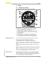
Depending on the switching function your relay output should carry
out, you can determine the switching direction by means of the slide
switch.
•
For maximum indication or overfill protection set the slide switch to
position max.
•
For minimum indication or dry run protection, set the slide switch
to position min.
The relay is energized if the yellow relay control lamp lights.
With the two keys you can change the LED indication strip and adjust
the switching point to the medium.
The keys are recessed to avoid unintentional changes of the settings.
To make an adjustment, use eg a small screwdriver.
If you press one of the keys for more than two seconds, the adjust-
ment range shifts automatically in the respective direction. The
greater the distance between emitting and receiving unit, the greater
the adjustment range of the indication. The LED indication strip
always shows a small section of the actual measuring range.
Pressing the "<--" key makes the sensor more sensitive. Pressing the
"-->" key makes the sensor less sensitive.
Press the respective key until the indication is within the LED indica-
tion strip. This means one or two LEDs on the LED indication strip will
light up.
Sensitivity adjustment


