background image

14

4 Mounting

VEGAMIP R61 • Receiving unit

35786-EN-171120

You have to remove these plugs before electrical connection.
NPT thread

In the case of instrument housings with self-sealing NPT threads, it is 

not possible to have the cable entries screwed in at the factory. The 

free openings for the cable glands are therefore covered with red dust 

protection caps as transport protection. The dust protection caps do 

not provide sufficient protection against moisture.

Prior to setup you have to replace these protective caps with ap-

proved cable glands or close the openings with suitable blind plugs.

4.2  Mounting instructions

If possible, install VEGAMIP 61 in a position where strong signal 

damping by the medium is expected.

Avoid mounting the instrument too close to the vessel wall. Reflec

-

tions from the vessel wall or from vessel installation can influence the 

switching accuracy.

Fig. 6: Installation position (top view)

The VEGAMIP 61 requires a minimum medium thickness to detect 

different products.

Dependent on the medium there will be a respective medium thick-

ness.
The properties of the medium are also dependent on the granulation 

size, the bulk density and the moisture content.

Some exemplary reference values for the min. strength of the me-

dium:

Medium type

Medium

Min. medium thickness

Plastic granules

PTFE, PS

> 1000 mm

PP, PE, HDPE, POM

> 500 mm

PA, PVC, PVDF

> 250 mm

Foodstuffs and wood

Flour

> 100 mm

Cereals, corn, rice

> 100 mm

Wood chips (dry)

> 500 mm

Wood chips (moist)

> 100 mm

Switching point

Medium thickness

Summary of Contents for VEGAMIP R61

Page 1: ...Operating Instructions VEGAMIP R61 Receiving unit Relay Document ID 35786 ...

Page 2: ... 3 2 Principle of operation 8 3 3 Packaging transport and storage 10 3 4 Accessories and replacement parts 10 4 Mounting 13 4 1 General instructions 13 4 2 Mounting instructions 14 5 Connecting to power supply 25 5 1 Preparing the connection 25 5 2 Connection procedure 26 5 3 Wiring plan single chamber housing 27 6 Setup 29 6 1 Adjustment elements 29 6 2 Adjustment 30 7 Maintenance and fault recti...

Page 3: ...afety instructions for Ex areas Take note of the Ex specific safety instructions for Ex applications These instructions are attached as documents to each instrument with Ex approval and are part of the operating instructions manual Editing status 2017 11 16 ...

Page 4: ...symbol on the front page of this instruction refers to the Docu ment ID By entering the Document ID on www vega com you will reach the document download Information tip note This symbol indicates helpful additional information Caution If this warning is ignored faults or malfunctions can result Warning If this warning is ignored injury to persons and or serious damage to the instrument can result ...

Page 5: ...all prevailing regulations and directives The instrument must only be operated in a technically flawless and reliable condition The operator is responsi ble for the trouble free operation of the instrument When measuring aggressive or corrosive media that can cause a dangerous situation if the instrument malfunctions the operator has to implement suitable measures to make sure the instrument is fu...

Page 6: ...ibility to other instruments must be ensured by suitable measures 2 6 Radio license for Europe The instrument is approved according to EN 300440 1 V1 5 1 2009 03 and EN 300440 2 V1 531 2009 03 and can be used without radio limitations 2 7 Radio license for USA Canada Operation is only permitted if the following two conditions are fulfilled The instrument must not emit interference radiation The in...

Page 7: ...nvironment is one of our most important duties That is why we have introduced an environment management system with the goal of continuously improving company environmental pro tection The environment management system is certified according to DIN EN ISO 14001 Please help us fulfil this obligation by observing the environmental instructions in this manual Chapter Packaging transport and storage C...

Page 8: ...label of the instrument or Enter the serial number manually in the app The scope of delivery typically consists of the following components Point level sensor VEGAMIP R61 receiving unit Documentation This operating instructions manual Supplementary instructions manual Plug connector for level sensors optional Ex specific Safety instructions with Ex versions If necessary further certificates The co...

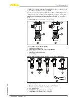
Page 9: ...for the instru ment The VEGAMIP 61 consists of the components 3 3 5 4 5 2 1 Fig 1 VEGAMIP 61 with plastic housing 1 Emitting unit VEGAMIP T61 2 Receiving unit VEGAMIP R61 with control electronics 3 Housing lid 4 Housing with control electronics 5 Process fitting Several antenna versions are available for different applications 1 2 3 5 4 Fig 2 Antenna versions 1 Threaded version internal horn anten...

Page 10: ...it damage or con cealed defects must be appropriately dealt with Up to the time of installation the packages must be left closed and stored according to the orientation and storage markings on the outside Unless otherwise indicated the packages must be stored only under the following conditions Not in the open Dry and dust free Not exposed to corrosive media Protected against solar radiation Avoid...

Page 11: ...g adapter Abrasion protection 40 80 C 40 176 C With high process temperatures exceeding 80 C you have to use a mounting adapter High temperature for the emitting and the receiv ing unit The mounting adapter High temperature can only be used with the threaded version internal horn antenna with PTFE cover x Fig 4 VEGAMIP 61 with mounting adapter High temperature 40 450 C 40 842 F x Length Mounting a...

Page 12: ...12 3 Product description VEGAMIP R61 Receiving unit 35786 EN 171120 x y Fig 5 VEGAMIP 61 with mounting adapter High temperature with extension 40 450 C 40 842 F ...

Page 13: ...xtended ambient condi tions acc to DIN EN IEC ANSI ISA UL CSA 61010 1 Protect your instrument against moisture ingress through the following measures Use a suitable connection cable see chapter Connecting to power supply Tighten the cable gland When mounting horizontally turn the housing so that the cable gland points downward Loop the connection cable downward in front of the cable gland This app...

Page 14: ...61 in a position where strong signal damping by the medium is expected Avoid mounting the instrument too close to the vessel wall Reflec tions from the vessel wall or from vessel installation can influence the switching accuracy Fig 6 Installation position top view The VEGAMIP 61 requires a minimum medium thickness to detect different products Dependent on the medium there will be a respective med...

Page 15: ...e non conductive materials Hence it is pos sible to measure through the wall of non conductive vessels Fig 7 Bulk solids vessel of plastic In metal vessels you have to mount VEGAMIP 61 on flanges or threaded sockets It is also possible to measure through a window In general all products such as glass ceramic and plastic are suitable as window material Max thickness of the window material Type of m...
Page 16: ...tion glass fitting In general the same as for metal vessels applies to concrete vessels due to the steel braining In general the same as for metal vessels applies to wood vessels due to the liquid absorption of the wood VEGAMIP 61 can be used for detection of products in pipelines In pipelines of non metallic products such as plastic or glass the meas ured product can be detected through the pipe ...

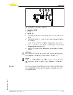
Page 17: ...n the sensor back max 180 to reach the required orientation of the polarisation marking 1 4 Hold the instrument in this position and tighten with the counter nut 3 Caution The housing must not be used to screw the instrument in Applying tightening force can damage internal parts of the housing Note In the case of VEGAMIP 61 with NPT thread the instrument seals in the thread itself Hence no counter...

Page 18: ... possible you can fill long sockets with a plastic or ceramic cylinder to avoid build up of bulk solids and dust deposits Select the material according to the diameter of the socket and adapt the length as far as possible to the shape of the vessel wall Secure the filling material against falling out or turning If using a fixing screw is technically not possible you can secure the material in the ...

Page 19: ...lly possible In very abrasive products the VEGAMIP 61 should be installed with a mounting adapter Abrasion protection This mounting adapter Abrasion protection is screwed onto the thread of VEGAMIP 61 like an adapter The mounting adapter Abrasion protection can only be used with the threaded version internal horn antenna with PTFE cover Abrasive medium ...

Page 20: ...s available in two tempera ture stages 40 250 C 40 482 F length x 150 mm 5 9 in 40 450 C 40 842 F length x 300 mm 11 8 in The mounting adapter High temperature can only be used with the threaded version internal horn antenna with PTFE cover x Fig 14 VEGAMIP 61 with mounting adapter High temperature 40 450 C 40 842 F x Length Mounting adapter High temperature As an option the high temperature mount...

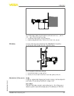
Page 21: ...should be mounted with anti vibration blocks or rubber buffers 1 2 Fig 16 Installation with vessel vibrations 1 Anti vibration blocks or rubber buffers 2 Window of non conductive material for example glass plastic etc Angle To get an optimal switching signal the two sensors must be aligned to each other The accuracy must be in a range of 5 Axis offset The axes of the two sensors can be offset up t...

Page 22: ... direction The emitting unit emits electromagnetic waves The polarisation plane is the direction of the electrical wave component Its position is marked on the instrument hexagon by polarisation markings For a reliable function the emitting and receiving units must be installed in the same polarisation direction If multiple instrument pairs are installed in one vessel the instrument pairs can be c...

Page 23: ...ctor can be positioned on the emitting unit side or on the receiving unit side In products with low dielectric value we recommend using an instru ment version with antenna extension because it focusses the signal optimally and has no signal loss On instrument versions with detach able horn antenna the antenna extension can be retrofitted To minimize false echoes take note of the polarisation plane...

Page 24: ... Mounting VEGAMIP R61 Receiving unit 35786 EN 171120 3 45 1 2 Fig 19 Possibilities for signal deflection 1 Metal plate for deflection of the microwave signal 2 Bent antenna extension 3 Polarisation marking ...

Page 25: ...d cable should be used Make sure that the cable used has the required temperature resist ance and fire safety for max occurring ambient temperature Use cable with round cross section for instruments with housing and cable gland To ensure the seal effect of the cable gland IP protection rating find out which cable outer diameter the cable gland is suitable for Use a cable gland fitting the cable di...

Page 26: ...e ends into the terminals according to the wiring plan Information Solid cores as well as flexible cores with wire end sleeves are inserted directly into the terminal openings In case of flexible cores without end sleeves press the terminal from above with a small flat head screwdriver the terminal opening is then free When the flat head screwdriver is released the terminal closes again 6 Check th...

Page 27: ...g circuit is open when there is a level signal line break or failure safe state Information The relays are always shown in non operative condition 3 2 1 Fig 21 Wiring plan receiving unit VEGAMIP 61 receiver 1 Relay output 2 Relay output 3 Voltage supply When connecting to a PLC the min switching capacity of the relay must be taken into account If necessary a correspondingly dimensioned resistor mu...

Page 28: ...1 Receiving unit 35786 EN 171120 1 RL RI UB Fig 22 Wiring plan receiving unit VEGAMIP 61 receiver when connecting to a PLC 1 PLC process control system Ri Internal resistance of the PLC RL Additional load resistance 6 8 8 2 kΩ UB Voltage supply ...

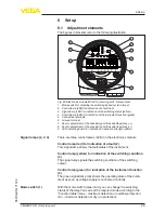
Page 29: ...vity and the switching delay 9 LED indicating board for indication of reception strength yellow There are three control lamps LED on the electronics module Control lamp red for indication of a fault 2 This signal lamp shows the fault status of the instrument Control lamp yellow for indication of the switching condition 3 The signal lamp signals the switching condition of the switching output Contr...

Page 30: ...ft more sensitive 6 2 Adjustment The microwave barrier can only be adjusted when it is uncovered Make sure that no measured medium or vessel installations are between the emitting and receiving unit Select the requested mode min max according to the function table The following function table provides an overview of the switching statuses depending on the set mode and level Level Switching status ...

Page 31: ...s With the two keys you can change the LED indication strip and adjust the switching point to the medium The keys are recessed to avoid unintentional changes of the settings To make an adjustment use eg a small screwdriver If you press one of the keys for more than two seconds the adjust ment range shifts automatically in the respective direction The greater the distance between emitting and recei...

Page 32: ...indicating strip you can see the actual receive level during adjustment When the indication moves to the right the instrument is less sensi tive to the left more sensitive In applications with products providing good signal damping for ex ample rocks ore sand cement and where buildup and contamina tion is expected you should adjust the instrument to more insensitive In this case the VEGAMIP 61 swi...

Page 33: ...pplications with products providing only weak signal damping eg plastic granules cereals you should adjust the instrument to more sensitive This way the VEGAMIP 61 switches very sensitively even with a relatively low coverage by the product Fig 42 LED indicating strip Setting for products with weak signal damping You can adjust the switching delay with the help of the LED indicating strip Push the...

Page 34: ...itching delay LED indication flashes If the indication moves to the right the switching delay will be longer to the left shorter The indication returns automatically to the indication of the actual receive level after approximately 10 s If possible simulate a filling between the emitting and receiving units with your hand or a metal sheet and check if the switching point is adjusted correctly If t...

Page 35: ...e Unfavourable installation location Mount the sensor emitter receiver at a location where there is a large quantity of measured product between the emitting and receiving units Mount the sensor emitter receiver at a location where there are no interfering installations or moving parts Electronics defective Press the mode switch If the instrument then does not change the mode the electronics modul...

Page 36: ... user In Ex applications only an electronics module with respective Ex ap proval may be used You can find all the information you need to carry out an electronics exchange in the handbook of the new electronics module 7 4 How to proceed if a repair is necessary You can find an instrument return form as well as detailed informa tion about the procedure in the download area of our homepage www vega ...

Page 37: ...es We use recyclable materials and have designed the electronics to be easily separable Correct disposal avoids negative effects on humans and the environ ment and ensures recycling of useful raw materials Materials see chapter Technical data If you have no way to dispose of the old instrument properly please contact us concerning return and disposal WEEE directive 2012 19 EU This instrument is no...

Page 38: ...op tional 80 C 176 F FKM A P FPM 70 16 06 Process seal Klingersil C 4400 Al2 O3 ceramic 316L Mounting adapter High temperature op tion 250 C 482 F Graphite Process seal Klingersil C 4400 Al2 O3 ceramic 316L Mounting adapter High temperature op tion 450 C 842 F Graphite Process seal provided by customer Al2 O3 ceramic 316L Materials non wetted parts Ʋ Ʋ Plastic housing Plastic PBT Polyester Ʋ Ʋ Alu...

Page 39: ...ver Flange DN 80 DN 150 ASME 3 6 10 Torque for NPT cable glands and Conduit tubes Ʋ Ʋ Plastic housing max 10 Nm 7 376 lbf ft Ʋ Ʋ Aluminium Stainless steel housing max 50 Nm 36 88 lbf ft Output variable Output Relay output DPDT 2 floating spdts Switching voltage max 253 V AC 253 V DC Switching current max 5 A AC 1 A DC Breaking capacity Ʋ Ʋ Min 50 mW Ʋ Ʋ Max 750 VA AC cos phi 0 5 40 W DC ohmic load...

Page 40: ...brasion protection 1 20 bar 100 2000 kPa 14 5 290 psig Ʋ Ʋ VEGAMIP 61 with mounting adapter High temperature 150 mm unpressurized IP 67 Ʋ Ʋ VEGAMIP 61 with mounting adapter High temperature 300 mm unpressurized IP 67 Process temperature thread or flange temperature Ʋ Ʋ VEGAMIP 61 threaded version inter nal horn antenna with PTFE cover 40 80 C 40 176 F Ʋ Ʋ VEGAMIP 61 plastic encapsulated antenna wi...

Page 41: ...ls Instruments with approvals can have different technical specifications depending on the version For that reason the associated approval documents of these instruments have to be carefully noted They are part of the delivery or can be downloaded under www vega com Instrument search serial number as well as in the download area 9 2 Dimensions VEGAMIP 61 housing versions 3 2 1 4 69 mm 2 72 ø 79 mm...

Page 42: ...d version 22 mm 0 87 83 mm 3 27 SW 46 mm 1 42 SW 46 mm 1 42 SW 60 mm 1 42 G1 A 1 NPT 83 mm 3 27 1 2 Fig 45 VEGAMIP 61 internal horn antenna threaded version 1 Internal horn antenna with PTFE cover threaded version G1 2 Internal horn antenna with PTFE cover threaded version 1 NPT ...

Page 43: ... 53 99 5 mm 3 92 ø 44 mm 1 73 Fig 46 VEGAMIP 61 encapsulated antennas 1 Encapsulated horn antenna with PTFE cover flange version 2 Plastic encapsulated antenna with PP cover 3 Mounting strap 4 Adapter flange VEGAMIP 61 horn antenna mm inch 38 mm 1 50 22 mm 0 87 SW 46 mm 1 81 3 94 ø1 58 ø1 89 4 72 x y 100 ø40 120 ø48 1 2 x y 1 2 x y G1 A 1 NPT 1 Fig 47 VEGAMIP 61 horn antenna 316L ...

Page 44: ... adapter with ceramic cover optional for VEGAMIP 61 with internal horn antenna threaded ver sion G1 with PTFE cover also with 1 NPT thread x 150 mm 5 9 in 40 250 C 40 482 F x 300 mm 11 8 in 40 450 C 40 842 F VEGAMIP 61 mounting adapter High temperature with extension 40 450 C 40 842 F 24 mm 0 95 ø 55 mm 2 17 x 61 mm 2 4 y z Fig 50 Mounting adapter with extension for front flush mounting for VEGAMI...

Page 45: ...des droits de propriété intellec tuelle Pour plus d informations on pourra se référer au site www vega com VEGA lineas de productos están protegidas por los derechos en el campo de la propiedad indus trial Para mayor información revise la pagina web www vega com Линии продукции фирмы ВЕГА защищаются по всему миру правами на интеллектуальную собственность Дальнейшую информацию смотрите на сайте www...

Page 46: ...5 Functional principle 10 M Medium 14 Mode 30 Mounting adapter 11 20 O Orientation of the sensor 21 P Pipelines 16 Polarisation direction 21 Potential equalisation 25 R Receiving unit 9 27 29 Repair 36 S Sensitivity adjustment 31 Service hotline 36 Shielding 25 Simulation 34 Switching delay 33 Switching point 14 T Threaded version 16 Type label 8 Type of vessel Concrete vessel 16 Metal vessels 15 ...

Page 47: ...47 Notes VEGAMIP R61 Receiving unit 35786 EN 171120 ...

Page 48: ...e of delivery application practical use and operat ing conditions of the sensors and processing systems correspond to the information available at the time of printing Subject to change without prior notice VEGA Grieshaber KG Schiltach Germany 2017 Phone 49 7836 50 0 Fax 49 7836 50 201 E mail info de vega com www vega com ...

Reviews: