


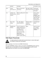


Maintenance and Diagnostics
are bad
Relay Relay
condition
indicator
ON - relay
energized.
OFF - relay
de-energized
None
Check against relay output
terminals 3, 4, and 5. If no relay
output, replace power supply
board.
CPU Board
Use the LED indicators on the CPU board to check the basic functioning of the gauge.
They are visible when you remove the explosion-proof housing pipe cap.
LED Indicators – CPU Board
If the LED band displays the Memory Corrupt pattern, call VEGA Field
Service to report this condition. The gauge does not operate if the FLASH
chip is corrupt.
CPU
LEDs
Description
Normal Condition
Error Condition Recommendation
Mem
Memory
corruption
OFF
Blink Pattern
1-CPU EEPROM
corrupt
2-Sensor EEPROM
corrupt
3-Both EEPROMs
corrupt
4-RAM corrupt
5-Memory mismatch
ON solid-
Combination of
errors
Check software
diagnostics. Call
VEGA Field
service.
HART
HART
communication
ON - blinks when
receiving HART
None
Check device and
21
Summary of Contents for DSGH
Page 2: ......
Page 4: ...Notes NOTES 4...
Page 6: ...Notes NOTES 6...
Page 14: ...Notes NOTES 14...
Page 24: ...Notes NOTES 24...
Page 26: ...Notes NOTES 26...
Page 27: ......


