


Maintenance and Diagnostics
CPU board
Label
Description
Count
Raw input signal coming from the preamplifier
GND
Logic ground
U5 pin 8
+5V power supply test point, referenced to logic ground
Jumpers
Jumpers JP1 and JP2 on the power supply board set the current loop source or sink
mode. The gauge does not use jumpers J1 through J4 on the CPU board.
Do not change the jumpers from the current setting without calling VEGA
Field Service.
Mode
Gauge Current Loop
Jumper Setting
Source mode
Self-powered
JP1 Pins 1-2, JP2 Pins 2-3
Sink mode
DCS-powered
JP1 Pins 2-3, JP2 Pins 1-2
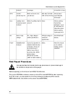
LED Indicators
Power Supply Board
LED
Description
Normal
Condition
Error Condition
Recommendation
+6V
+6V DC
voltage level to
electronics
ON
OFF - electronics
are not receiving
+6 V DC required
for functioning
6 V on pin 8 of terminal strip
(Pin 9 can be used as ground
reference. Check fuse on power
supply board. Check power input
terminals 1 and 2.
+24V Analog output
loop voltage
ON
OFF - 24 V not
present on 4 ... 20
mA output and
HART
communications
Check loop wiring and jumpers JP1,
JP2 on power supply board.
Replace power supply board.
20
Summary of Contents for DSGH
Page 2: ......
Page 4: ...Notes NOTES 4...
Page 6: ...Notes NOTES 6...
Page 14: ...Notes NOTES 14...
Page 24: ...Notes NOTES 24...
Page 26: ...Notes NOTES 26...
Page 27: ......


