VEC-1002K Owner's Manual
2 Meter FM Receiver Kit
14
!
!
2. Make a jumper with a .275" span. Install at JMP2 and solder.
!
!
3. Make another jumper with a .275" span. Install at JMP3 and solder.
!
!
4. Make a jumper with a .3" span. Install at JMP4 and solder.
!
!
5. Make a second jumper with a .3" span. Install at JMP5 and solder.
Congratulations--you've installed most of the "small stuff", and you're well on
the way to completing the kit! Now, we'll begin installing larger and taller
components, and your receiver will take shape more rapidly!
Phase 8: Miscellaneous Items
!
!
1. Locate the 10.7 MHz ceramic filter FL1 (10.7J). This device looks
something like a square disc ceramic capacitor with three pins on the
bottom. FL1 is not polarized, and it can be installed either way.
Install and solder in place.
!
!
2. Locate the 455 KHz ceramic filter FL2 (55D or 55F). This is a small
black cube with three pins, and it will only fit one way on the PC
board. Install and solder.
!
!
3. Find the 3.5 mm stereo mini-headphone jack. Install at J2, making
sure it is fully seated and level. Solder.
!
!
4. Find the RCA "phono" type jack. Install at J1, making sure it is fully
seated and level. Solder.
!
!
5. Locate push-button power switch SW1. Install and check seating
before soldering.
!
!
6. Locate Y1, a 10.245 MHz crystal. Install and solder.
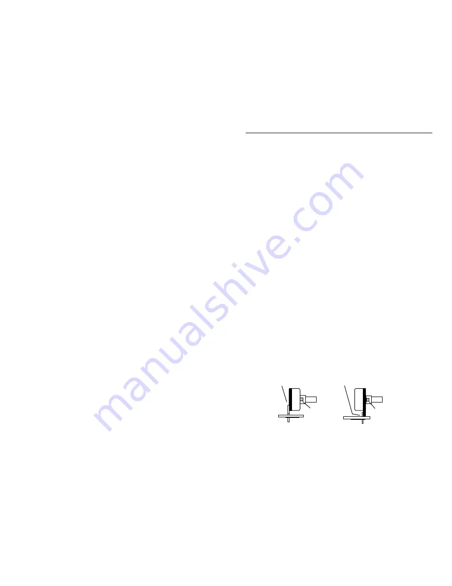
The front-panel controls (tuning, squelch, volume) are mounted next. Before
installing these parts, inspect the type of potentiometer supplied with your kit. If
the pins are located on the
front
side of the pot, use the
front set of mounting
holes
on the PC board for installation. If the pins are on the
rear
, use the
rear
set of mounting holes
(see following diagram). Also, using side cutters, remove
the key tab from the side of each pot prior to installation.
Rear pins use rear holes.
Front pins use front holes.
Nip off tab.
Nip off tab.


