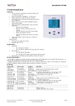
Humidistat TCY-BH
Doc: 70-00-0142, V1.4, 20160912
© Vector Controls GmbH, Switzerland
Page 2
Subject to alteration
www.vectorcontrols.com
Technical specification
Important notice and safety advice
This device is for use as operating controls. It is not a safety device! Where a device failure endangers human life
and/or property, it is the responsibility of the client, installer and system designer to add additional safety devices to
prevent a system failure caused by such a device failure. Ignoring specifications and local regulations may cause
equipment damage and endangers life and property. Tampering with the device and misapplication will void warranty.
Power supply
Operating voltage TCY-BH
TCY-BH-230
24V AC/DC ± 10 %, 50…60 Hz
210 – 250V AC 50/60 Hz
Power consumption
Max. 1W, 1.5 VA
Electrical connection
Terminal Connectors,
wire 0.34…2.5 mm
2
(AWG 24…12)
Deluxe type only:
Power backup for real time clock
Min 48h if charged for 24h
Signal inputs
Humidity input:
Range
Accuracy
Hysteresis
Element: Polymer-Based Capacity Sensor
0…100 % r.H.
10%...90% r.H.
5.0 %
0…10% and 90…100%
7.0 %
±1% r.H.
Temperature input
Range
External NTC (Sxx-Tn10 sensor):
-40…70°C (-40…158 °F)
Accuracy
-40…0 °C (-40…32 °F): 0.5 K
0…50 °C (32…122 °F): 0.2 K
50…70 °C (122…158 °F): 0.5 K
Signal outputs
Digital switching outputs
Switching type
AC switching power
DO1…DO2
Relays
2(1.2) A, 250VAC (max fan power 300W)
Environment
Operation
Climatic conditions
Temperature
Humidity
To IEC 721-3-3
class 3 K5
0°C …50°C (32°F…122°F)
<95% R.H. non-condensing
Transport & storage
Climatic conditions
Temperature
Humidity
Mechanical conditions
To IEC 721-3-2 and IEC 721-3-1
class 3 K3 and class 1 K3
-25°C…70°C (-13°F…158°F)
<95% R.H. non-condensing
class 2M2
Standards
conform according to
EMC Directive 2004/108/EU
LV Directive 2006/95/EU
EN 61 000-6-1/ EN 61 000-6-3
Product standards
Automatic electrical controls for
household and similar use
EN 60 730 –1
Degree of protection
IP30 to EN 60 529
Safety class
TCY-BH
TCY-BH-230
III (IEC 60536)
II (IEC 60536)
Overvoltage category
TCY-BH
TCY-BH-230
II (EN 60730-1)
III (EN 60 730-1)
Housing
Cover, back part
Mounting plate
Fire proof ABS plastic (UL94 class V-0)
Galvanized Steel
General
Dimensions (H x W x D)
Front part:
Power case TCY-BH:
Power case TCY-BH-230
88 x 88 x 21 mm (3.5” x 3.5” x 0.8”)
ø 58 x 32 mm (ø 2.3” x 1.3”)
60 x 50 x 32mm (2.4 x 2.0 x 1.3 in)
Weight (including package) TCY-BH
TCY-BH-230
260g (9.2 oz)
295g (10.4 oz)
Selection of devices and sensors
External temperature sensors: Use only our approved NTC sensors to achieve maximum accuracy. Recommended is
SDB-Tn10-15 as Duct sensor and SOA-Tn10 as outdoor sensor.
Binary auxiliary devices: E.g. humidifiers, de-humidifiers and fans. Do not directly connect devices that exceed
2(1.2)A. Observe startup current on inductive loads!


