background image


Humidistat TCY-BH


Doc: 70-00-0142, V1.4, 20160912 

© Vector Controls GmbH, Switzerland 

Page 3 

Subject to alteration 

www.vectorcontrols.com 

Dimensions mm (inch) 
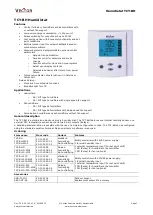
 

Connection diagram 


Description

:  

Connections depend on parameter CP10 and CP11! (See page 10) 
CP10 

DO1 

DO2 

RT 

CP10 = 0 

Humidify 

Dehumidify 

Temperature input for 

setback 
NTC 10kΩ @ 25°C (77°F) 

CP10 = 1 

Humidify 

CP11 = ON: FAN 

CP10 = 2 

If CP11 = ON: FAN 

Dehumidify 

N   L 

Power In 

DO1 

Relay 2A 

NTC 

10kΩ 

1     2 

G0 G 

24VAC/DC 

5      6 

Q23 Q24 

3     4 

Q13 Q14 

DO2 

7      8 

B1    M 

RT ext. 

NTC10k


TCY-BH 

Power In 

DO1 

Relay 2A 

NTC 

10kΩ 

1     2 

N   L 

230VAC 

Q24 

DO2 

7      8 

B1    M 

N   L 

Q14 

RT ext. 

NTC10k


TCY-BH-230 

5      6 


88 (3.5) 

32 (1.2) 

21  

(0.8) 

8

8

 (

3

.5

5

8

 (

2

.3

32 (1.2) 

21  

(0.8) 

TCY-BH-230


Enlarged back part for TCY-BH-230 
Space required in flush mounting box: 

(H x W x D)  

60 x 50 x 32mm (2.4 x 2.0 x 1.26 in.) 
 
Distance for mounting screws: 

Horizontal and vertical:  

45 to 63mm (1.8 to 2.5 in.) 
 

TCY-BH 

Summary of Contents for TCY-BH

Page 1: ...tion The TCY BH is a stand alone electronic binary humidity stat The TCY BH features one internal humidity sensor one external NTC temperature sensor input and two binary outputs Relays A detailed par...

Page 2: ...witching type AC switching power DO1 DO2 Relays 2 1 2 A 250VAC max fan power 300W Environment Operation Climatic conditions Temperature Humidity To IEC 721 3 3 class 3 K5 0 C 50 C 32 F 122 F 95 R H no...

Page 3: ...umidify CP11 ON FAN CP10 2 If CP11 ON FAN Dehumidify N L Power In DO1 Relay 2A NTC 10k 1 2 G0 G 24VAC DC 5 6 Q23 Q24 N L 3 4 Q13 Q14 N L DO2 7 8 B1 M RT ext NTC10k TCY BH Power In DO1 Relay 2A NTC 10k...

Page 4: ...er capacitor The time does not need to be re entered after a power failure Error messages The TCY BH may display the following error condition Err1 Humidity sensor faulty The humidity sensor is damage...

Page 5: ...time schedule Pro1 Pro4 by using UP DOWN keys and pressing the ENTER key 1 Enable or disable the Pro1 time schedule Choose ON or OFF with the UP DOWN keys The following steps will only be accessible...

Page 6: ...key will show CODE 2 Select a password using UP or DOWN buttons Select 009 in order to get access to the user parameters 241 for controls parameters Press OPTION after selecting the correct password 3...

Page 7: ...cles and thus the wear on associated equipment 0 100 3 CP 08 Delay OFF Minimum running time MM SS Prevents a too short running cycle for the control output by setting a minimum running time 00 00 to 9...

Page 8: ...point towards a defined TSET set point CP15 depending on the outdoor temperature Temperature setback becomes active when the outside temperature drops below the activation limit of temperature setback...

Reviews: