background image


Parts name: 

Main unit


Item No. 

  Part Name   

Description 

1, 2 

Nut 

Handle Bracket Assembly 

Handle clamping element 

Handle Bracket Assembly 

Lead free soldering iron handle assembly 


Handspike 


Pressure adjusting screw 


Feeder tube assembly 

Optional   

Solder Wire Axis 

Install Solder Wire 

Solder Wire holder 

Install Solder Wire Axis 

10 

Metal plate 


11 

Cleaning sponge 


12 

Pedal Switch 

Optional Part 


Feeder Tube (0.8m) 


Guide Tube Assembly   

(Using for top Feeding )


Guide Tube Assembly   

(Using for bottom Feeding)


Summary of Contents for 963D

Page 1: ...Soldering Station Operation Manual Thank you for purchasing a Self Feeder Lead Free Soldering Station Please read this manual before operating the unit Store this manual in a safe easily accessible pl...

Page 2: ...soldering Don t rap the soldering iron against the work bench to shake off residual solder or otherwise subject the iron to severe shocks Don t wet the appliance and don t disconnect the appliance wit...

Page 3: ...Power consumption of unit 90W Motor Step Motor Feeding speed About 2 7mm s 27mm s 36 s 360 s Feeding Length 0 150mm Feeding Interval Time 0 2 7s Returning Time 0 0 9s About 0 25mm Speed 360 s Feeding...

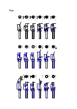
Page 4: ...ring Tip in accordance with Soldering Point Choose Solder Wire Ring in accordance with Solder Wire diameter Choose Feeder Tube in accordance with Solder Wire diameter Choose Guide Tube Assembly in acc...

Page 5: ...SECTION 6 Product picture and parts name 10 11 8 6 4 3 2 1 9 12 7 5 Main Unit 17 16 15 14 13 Feeder Tube Assembly 0 46m Short Tube Feeder Tube Assembly 0 8m Long Tube Feeder Tube 0 46m...

Page 6: ...ring iron handle assembly 5 Handspike 6 Pressure adjusting screw 7 Feeder tube assembly Optional 8 Solder Wire Axis Install Solder Wire 9 Solder Wire holder Install Solder Wire Axis 10 Metal plate 11...

Page 7: ...feeder tube head and then tighten the screw Installation of Long Tube Screw off the black nipple of handle assembly install the handle into the connector and screw on the black nipple again Unscrew th...

Page 8: ...ering Iron NOTE Please be careful not to break heating element when screw off black nipple to install connector If step on Pedal Switch or press down the red Touch Switch the solder wire can t be sent...

Page 9: ...es the interval time is 0 second to 2 7seconds The resolution is 0 3 second namely each digit denotes 0 3 second The setting method is the same as Feeding Speed Example When the digit is set as 1 the...

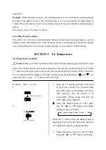
Page 10: ...tion can be adjusted password is OK or the password is initial While setting the temperature normally the heating element is off If the button is pressed less than one second the present temperature s...

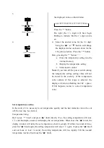
Page 11: ...temperature value outside of this range is selected the display will return to flashing the 100 s place If this happens reenter a correct temperature value Set temperature on line In the work if it is...

Page 12: ...r switch 2 Continue holding down the and button until the display shows 3 When the display shows the station is in parameter input mode Input Previously Password 4 Press the button the display shows a...

Page 13: ...lately two passwords are identical Note The word of password is from 0 to 9 ten words If not the changed password is unsuccessful SECTION 11 Set Working Mode The unit is design with many working modes...

Page 14: ...he unit comes into working mode setting state and pressing or button will change displayed value as shown below 0 1 2 3 4 5 6 7 0 1 2 3 4 5 6 7 2 After selecting the working mode press down The workin...

Page 15: ...with thermometer and write down the reading 3 Press button not loose and press the and button simultaneously the unit enters into calibrating temperature mode 4 At the moment the 100 s digit of LED d...

Page 16: ...to form a protecting film on tinned layer of soldering tip so it can prevent the oxidation at high temperature and failure of heat transport 3 If the tinned part of soldering tip has black oxide it ca...

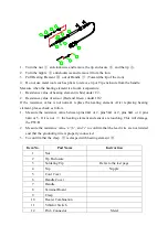
Page 17: ...e the heating element After replacing heating element please check as follow 1 Measure the resistance value between pins 4 1 or 2 pins 5 1 or 2 pins 6 1 or 2 pins 6 4 or 5 If it is not the heating ele...

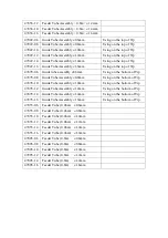
Page 18: ...se holder on the rear side of the unit with screwdriver 3 Remove the broken fuse and replace it with a new one 4 Fix the fuse holder SECTION 18 Replaceable Part Item No Parts Name Instruction 47442 Pe...

Page 19: ...e bottom of Tip 47478 0 8 Guide Tube Assembly 0 8mm Using on the bottom of Tip 47478 1 0 Guide Tube Assembly 1 0mm Using on the bottom of Tip 47478 1 2 Guide Tube Assembly 1 2mm Using on the bottom of...

Page 20: ...5 4 5 3 4 5 1 R 0 2 R 0 2 R 1 200 H 200 J 200 S K 200 K 200 3 C 4 2 2 12 15 12 12 12 12 12 12 12 17 12 12 4 4 2 3 7 3 2 3 5 2 4 3 1 6 2 5 1 2 R 0 5 10 10 12 12 12 12 0 5 0 5 0 5 0 5 0 5 200 4 2 D 200...

Reviews: