LVP615 series user manual
60
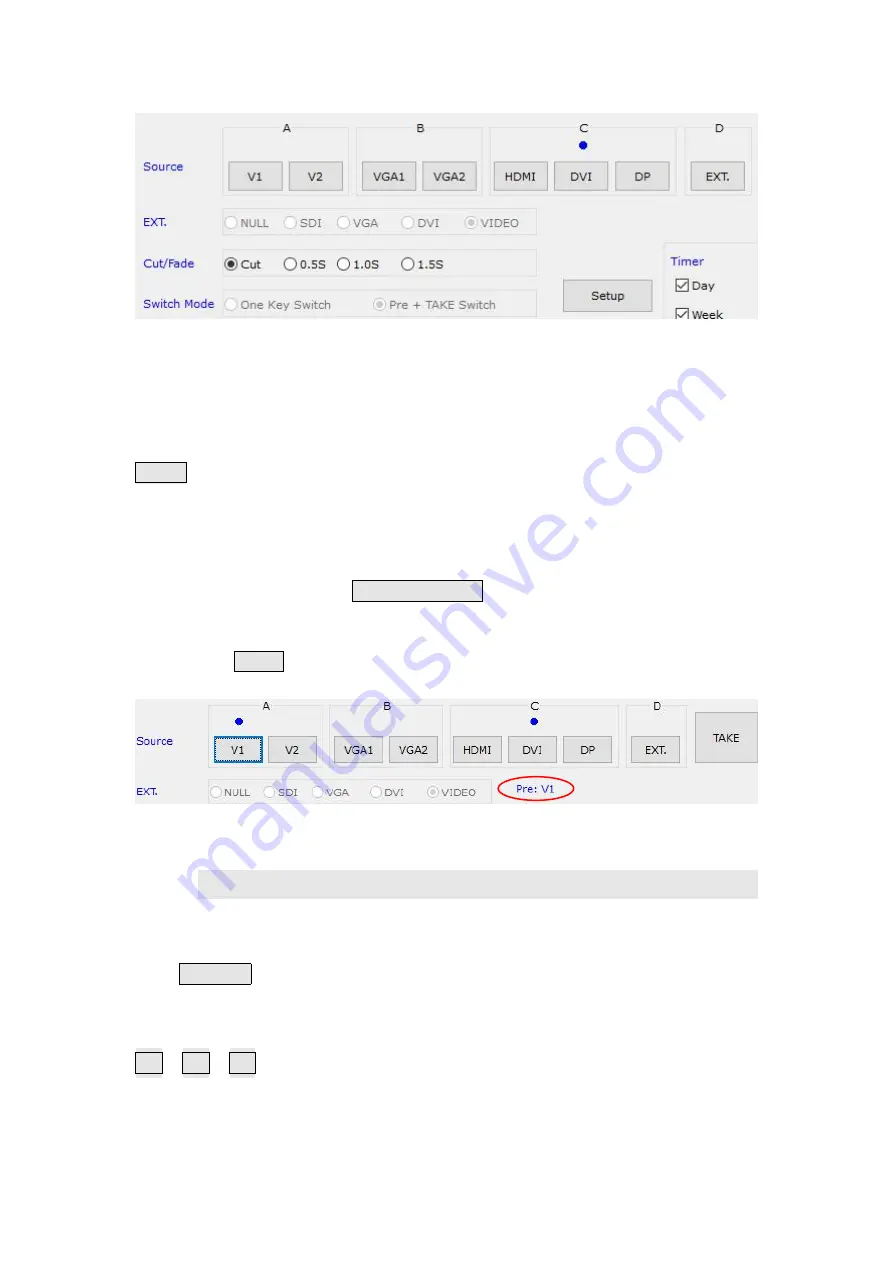
The buttons of the signal area respectively represent the corresponding keys and status
indicators in the panel of the processor.
After the device is successfully connected, the software will read the input signal source
you currently selected and the blue indicator above it will turn on. If the blue indicator
illuminates normally, it means the input signal source you currently selected is valid;
however, if the blue indicator blinks, it means there are no valid signal input.
AUTO
:
VGA automatically adjust button, only available for VGA1, VGA2 and EXT.VGA.
Switching effect selection, can select cut (seamless switching) and fade in / fade out (0.5s
1s 1.5s) switching.
Switching mode:
Default switching mode is one
one key switch
, this moment press signal button, input
switchs to relative signal;
If select pre +
TAKE
switching, the signal area become the style as below,
3
)
Selecting function and mode
The buttons in this area used for PIP, TEXT (Text Overlay), BYPASS, FREEZE, MOSAIC
PIP/PBP:
PIP switch, used to open or close PIP mode, meanwhile the bright point
above the button indicates the mode open or not.
M1
、
M2
、
M3
:
PIP mode buttons, the blue bright point above the mode button shows
which mode you have selected.
Summary of Contents for LVP615 series
Page 1: ...LVP615 series LED HD Video Processor User Manual Contents...
Page 12: ...LVP615 series user manual 12 RS232 cable order...
Page 82: ...LVP615 series user manual 82 2 PIP Display...
Page 83: ...LVP615 series user manual 83 PIP operation interface as the picture above operation steps...
Page 85: ...LVP615 series user manual 85 Interface of PIP Signal selection...
Page 89: ...LVP615 series user manual 89 1 Output Resolution...


