VarTech Systems VT084XHB User Manual Download Page 4


X-Series  All Weather User Guide                                                    4                                                                                          150-092 

1.4


Wiring Connections (Cont’d)


Power Connection


The LCD can be ordered as either AC powered or DC powered. The power receptacle is 
located near the lower rear housing on the back of the LCD. 
 

DC POWER

 - The cable is 10 ft. (3m) long and has two leads, the  and the Black—for 

direct connection to the DC voltage source. Connect these flying leads to the corresponding 
polarity on your voltage source primary terminals. 


CAUTION: MAKE SURE YOU ARE CONNECTING POWER  

TO THE CORRECT POLARITY! 

AC POWER

 - An external power supply adapter is supplied that will accept any voltage and 

frequency from 110 to 250 VAC and 47 to 63 Hertz. The standard AC power plug supplied is 
for 120 VAC 60 Hz most normally found in North America. 

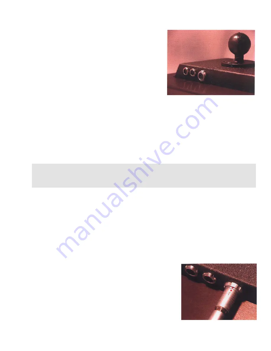
Quick Connect Cable Connector


The LCD uses a similar style of connector for both 
power and video, although they are not interchangeable. 
To install the cable connector into the receptacle on the 
unit, first make sure that the cable connector and the 
receptacle are lined up properly. Then simply push the 
connector into the receptacle until you feel or hear a 
snap. The connection is now securely made and 
positively retained. To disconnect, push the outside ring 
on the connector towards the receptacle while 
simultaneously pulling lightly on the cable until it is free. 

DO NOT USE ANY TOOLS!


VGA Computer Video Connection


The video receptacle is larger than the power receptacle and is located adjacent to the power 
receptacle on the lower rear of the LCD. The cable is 20 ft (6m) long and has a standard DB-
15 female connector at the far end. Insert the round connector on the cable into the 
receptacle. Plug the other end of the cable into the computer Video source and tighten 
screws. No special video adapter software is needed. 
Windows will automatically find and apply the best generic 
driver. If you are prompted by Windows to set up the display 
settings, be sure to choose 800x600 resolution and 16-bit 
color 
 

Summary of Contents for VT084XHB

Page 1: ...ide Read these instructions completely before attempting to operate your new Color Display X Series All Weather Displays VT084XHB VT104XHB VT121XHB Solutions for Demanding Applications Industrial CRT and Flat Panel Displays VARTECH S Y S T E M S I N C ...

Page 2: ...Display Features 3 3 1 Hampshire TSHARC Driver 13 2 2 Unpacking The Display 3 3 2 Install TSHARC Driver 13 19 2 3 Panel Mounting 3 2 4 Wiring Connections 3 4 Section 4 2 5 Signal Quality 5 Display Specifications 20 21 Section 2 Getting Started 6 2 1 Setting up the Computer 6 2 2 Operating Controls 7 2 3 On Screen Display 8 12 ...

Page 3: ... this be done by a qualified ma rine electronics installer with every effort made to maintain exact dimensional integrity Doing so will allow for a trouble free installation and maintain the sealing capabilities designed into the bezel without the need for additional sealing materials We understand that sometimes the sur face is not perfectly flat and that it may be necessary to supplement our gas...

Page 4: ...changeable To install the cable connector into the receptacle on the unit first make sure that the cable connector and the receptacle are lined up properly Then simply push the connector into the receptacle until you feel or hear a snap The connection is now securely made and positively retained To disconnect push the outside ring on the connector towards the receptacle while simultaneously pullin...

Page 5: ... such as radar and microwaves Splitting the video signal also splits the strength of the signal If your installation requires more than one monitor to be driven from a single video source it is highly recommended that a video signal booster line driver be used in the circuit Some splitters are available with an integral line driver Regardless of whether or not a line driver is used single cable le...

Page 6: ...tton select Settings Control Panel Display Settings When this window opens you will see in the lower right part of the window a selection of resolutions Choose 800x600 resolution On the left choose the color setting of High Color 16 bit Apply the proper setting and Accept when asked by Windows If you have another display connected for example the LCD of a notebook computer that display will now ha...

Page 7: ...ightness Controls Located next to the Power on LED are two buttons for controlling the brightness of the display The button with the large sun symbol when either repeatedly pressed or when held for several seconds will cause the brightness to decrease The very brightest setting is for operation when the ambient light is at a maximum This can be stepped down in increments to the lowest setting whic...

Page 8: ...riable may be user selected from the miscellaneous menu The right and left keypad buttons are used to scroll through items within the main menu The selected item will then be highlighted The SELECT key is used to open and close the OSD menu After in OSD menu SELECT key is also defined as the CONFIRM key to activate the highlighted item User Interface Buttons Select Button Select the currently high...

Page 9: ...m a warning message No Signal is displayed by the OSD until the supported input source is detected by the system OSD Main Menu The figures below are the OSD main menu icons that are displayed when the OSD is activated To choose a setting use the Left and Right arrows to move from one icon to the next When you have selected the menu choice you want push the Select button Input Interface Setting Not...

Page 10: ...s to adjust the value and Select Exit button to save the new value and return to the item selection on this PC Display menu Note that contrast adjustment controls the relative differentiation between lighter and darker pixels Black Level Adjustment Adjust the black level components of the displayed image There is a slider bar graphic depicting the relationship between the current black level setti...

Page 11: ... Position Press the Left and Right keys to move the screen left or right by moving the analog capture window V Position Press the Left and Right keys to move the screen up or down by moving the analog capture window Miscellaneous When the Miscellaneous icon is selected the following icons will appear To make a menu selection use the Left and Right arrows When the desired icon is chosen use the Sel...

Page 12: ...Display OSD Cont d Factory Reset Press Menu key to reset all user settings and then confirm user settings those stored in NVRAM will be lost This feature helps users return back to normal display especially when users change onboard firmware ROM and the panel ...

Page 13: ...be logged on as a network administrator If you have questions about the touch controller or wish to download the latest version of the driver go to www hampshiretouch com and download the driver for the TSHARC12 that matches your operating system 3 1 Hampshire TSHARC Touch Screen Driver 3 2 Installing the TSHARC Driver 1 If you have down loaded the driver from the internet you must run the self ex...

Page 14: ...ontrol panel consists of five tabs Each tab provides you with tools that can be used to modify the TSHARC driver to meet your needs Calibration Calibration Skew Multi monitor support General Right mouse button and Event area adjustment Other Touch Sound Offset Task Bar Touch Modes Normal Touch Down Touch Up Test Drawing test touch mode test Default Touch Controller Settings for MPC Panel Series TS...

Page 15: ...lay Distance from the edge 4 5 and 8 wire touch screens are constructed using various materials and linearization patterns Some manufacturers linearization patterns cause a straight line to bow near the edges of the overlay Because of the varied linearity that exists between touch screen types it may be necessary to calibrate the edges of the touch screen more concisely By allowing the user to cal...

Page 16: ... attach more than one up to eight as determined by the video card touch screen monitor to a computer system To use this feature you must have a display driver card that supports more than one monitor and you must have separate TSHARC touch screen controllers for each monitor on separate com ports You may also mix and match your com ports for the desired configuration For example you may have a tou...

Page 17: ...will graphically display your X and Y registration When the red and green dotted lines are aligned to the solid square lines of the display You may use the buttons on screen or the arrows on your keyboard to adjust the skew Right Click Event Area Since the majority of touch applications do not utilize a right click mouse function the default settings do not allow for a right mouse button click 1 Y...

Page 18: ...r function in the task bar properties for this to function 1 Enable the task bar 2 Identify where the task bar is located usually at the bottom of your display 3 Define the distance from the edge that you would like the task bar to be displayed Touch Modes You may change the way that your TSHARC controller reports a touch Normal Same as a standard mouse the touch point is defined by a touch down a...

Page 19: ...Touch double touch and right click in the touch test area to see that your touches are set properly The check boxes will display the function as it occurs Drawing Test Use this test to verify your calibration and insure that you have configured your TSHARC controller for drawing and writing applications ...

Page 20: ...resolution Cables Connectors Power 20 ft 6m Sealed Quick connect to 2 wire pigtail DC PC Video 20 ft 6m Sealed Quick connect to 15 pin D SUB M PC Serial 20 ft 6m Sealed Quick connect to 9 pin D SUB F Bezel Milled Aluminum Anodized Black or Gray Bright Dipped Sealed to NEMA 6P IP68 Mounting RAM Pedestal Mount or Panel Mount with rear stud mounting kit Operating Temperature Air Ambient 0 to 50ºC 32 ...

Page 21: ...HB Bezel Height 7 50 254mm 8 13 207mm 9 20 234mm Bezel Width 9 40 318mm 11 60 295mm 13 00 330mm Case Depth 2 12 54mm 2 12 54mm 2 12 54mm Cutout Height 6 50 1 65mm 7 13 181mm 7 96 202mm Cutout Width 8 40 213mm 9 60 244mm 9 60 244mm VT084XHB VT104XHB VT121XHB 3 9 lbs 1 7 kg 4 2 lbs 1 9 kg 6 0 lbs 2 7 kg VT084XHB VT104XHB VT121XHB 12W 14W 15W ...

Page 22: ... 150 092 150 090 001 12 30 05 VARTECH SYSTEMS HEADQUARTERS 11529 Sun Belt Ct Baton Rouge Louisiana 70809 Toll Free 800 223 8050 International Phone 001 225 298 0300 Fax 225 297 2440 E mail sales vartechsystems com www vartechsystems com ...

Reviews: