12
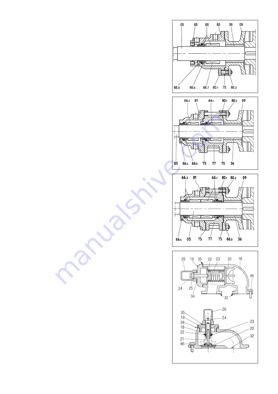
11.9 Removing the ST4, ST5, ST6 single mechanical seal (see fig. 16)
❑
Unscrew the screw (80.1) and move the seal box (80) carefully along the shaft,
to avoid breaking the rear oil seal V ring (68). The rotation portion of the seal (66.7)
can thus be uncovered.
❑
Loosen the grub screws and free the rotating seat of the seal. To remove it, it is
sufficient to slide it along the shaft, taking carre not to damage the internal gas-
ket.
Note: a mechanical seal (66) consists of two flat radial seats, one of wich (66.7)
is mounted in such a way as to rotate with the shaft.
The second seat (66.2) is stationary and the sealing action is ensured by the con-
tact created between the two seats.
❑
Check all the seal components. If there are clear signs of damage, replace the
seal as described under section 13.
11.10 Removing the ST7 double mechanical seal (see fig. 17)
❑
Unscrew the screws (80.1) and remove the seal box (81), taking care not to dam-
age the gasket (75). If the gasket is damaged, it must be replaced.
❑
Loosen the grub screws of the rotating part of the mechanical seal (66.2) and
remove it by sliding it carefully along the shaft, taking care not to damage the
internal gasket.
❑
Repeat the operation with the second seal box (77) and the second mechanical
seal (66.1).
❑
Check the state of the two mechanical seals and if there are any signs of damage,
especially on the gaskets, replace them as described in paragraph 12.5.
11.11 Removing the ST8 double mechanical seal (see fig. 18)
❑
Unscrew the screw (80.1) and remove the rear seal box (81), taking care not to
damage the gasket (75). If the gasket is damaged, it must be replaced.
❑
Loosen the grub screws of the rotating parts of the mechanical seals (66.1 and
66.2) and remove them by sliding them carefully along the shaft, taking care not
to damage the internal gaskets.
❑
Check the state of the two mechanical seals and if there are any signs of damage,
especially on the gaskets, replace them as described in paragraph 12.6.
11.12 Removing the shaft bush
❑
Dismount the pump completely as indicated for removing the rotor. Use a press to
force the shaft bush out of the rear cover or pedestal if it is worn. Mount the new
shaft bush in the same way.
❑
For the V 200, heat the rear cover to 80 deg C and insert the bush. Wait for it to
cool. Use a lathe to bring the hole up to tolerance as instructed by the manufac-
turers.
11.13 Removing and disassembling the by-pass relief valve (see fig. 19)
❑
Remove the entire relief valve assembly, unscrewing the screws (46), taking care
not damage the gasket or gaskets (32). If these are damaged, they must be
replaced.
❑
Remove the cap (26), the gasket (35) and loosen the lock nut (25) if fitted.
❑
Remove the cover (19), taking care not to damage the gasket (34). If the gasket
is damaged, replace it.
❑
Remove the valve washer (22), the spring (23) and the valve poppet (20).
❑
Chek the state of wear of the poppet and of its seat on the by-pass casing (18)
and replace if necessary.
❑
Chek the state of wear of the poppet and of its seat on the by-pass casing (18)
and replace if necessary.
❑
Check the spring and washer and replace if necessary.
❑
Assemble the valve by proceeding in reverse order.
Note: For the pressure setting, see paragraph 10.5. We reccomend setting the
valve at 1 bar more than the delivery pressure.
fig.16
fig.18
fig.17
fig. 19


