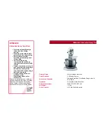
background image

20

CC

F

dL

Fig. 2. 

Belt tension

t

o


rePlaCe


a


lIftInG


aCtuator

:

Lift the bowl arms to the top position.
Lower the bowl arms to a pressure relief point set at approx. 

midway.

It is very important that the bowl arms are low-

ered to a pressure relief point before disassem-

bling the lifting actuator.

Cut the power to the machine by removing the plug from the 

socket.

Remove the three plugs for the reed contacts on the actuator.
Remove the lifting actuator from the bowl arms by removing 

the pins and axle.
Remove the cotter pin that secures the actuator at the top.
Remove the cable to the actuator and lift the actuator out 

from the mixing machine.
Install the new actuator.
Connect the machine to the power supply.

If replacing the lowest actuator fittings, use Lochtite 270 to 

tighten the fittings

.

t

o


rePlaCe


a


belt

:

The old belt can be removed by loosening the belt tightener.

Installing a new belt:

1. 

Place the belt in the wheel groove.

2. 

Tighten the belt using the belt tightener 

3. 

Tighten the belt until the belt can be bent approximately 

23/64” 

(dL)

 at a pressure of approx. 19 lb 

(F)

, see 

Fig. 

2

.

4. 

Run the machine with a regular production load for ap-

proximately 10 min.

5. 

Check the belt tension by measuring its elasticity. If the 

elasticity has changed, retighten as described in point 3.

The belt tension should be checked every 6 months.

If there is not enough belt tension, the belt will wear out 

quickly, and if there is too much tension, there is a risk that 

the life-span of the bearings will be considerably shortened.

Then follow the section 

“Fine-tuning the reed contacts 

and CE microswitch”

.

The lifting actuator has 3 proximity detectors (reed contacts) 

that check the position of the bowl.

r

ePlaCInG


the

 r

eed


ContaCtS

:

Remove the incorrectly charged contact and install the new 

contact according to 

Fig. 3

. Connect the cable as shown in 

the illustration on 

page 14

.

Follow the instructions below to secure the reed contact in 

the correct position.

f

Ine

-

tunInG

 r

eed


ContaCtS


and

 Ce 

mICro

-

SwItCh

:

Check that the location of the reed contacts matches up 

with the marks in 

Fig 3

.

Connect the reed contacts with the matching cables – see 

illustration on 

page 16

.

Adjust the three contacts and the CE microswitch according 

to the following sequence:

1.   Adjusting the top reed contact:

Contact 

A

 determines the top position of the bowl.

The contact must be positioned in accordance with the 

mark in 

Fig. 3

.

Raise the bowl to the position corresponding to mark 

X, 

Fig. 5

.

Adjust the top reed contact upwards until the reed LED 

lights up – it is important to stop adjusting once the LED 

lights up!

2.  Adjusting CE-microswitch:

ERGO60 

and 

ERGO100

, se 

Fig. 4

page 24

.

ERGO150

, se 

Fig. 4a

page 24

.

3.  Adjusting the reed contact for the JOG function

Contact 

B

 determines where the machine’s JOG function 

starts, see also “Bowl lifting and JOG function” on page 3.

The contact must be positioned as shown in 

Fig. 3 

and 

does not require any further adjustment.

4.  Adjusting the bottom reed contact:

Contact 

C

 determines the bottom position of the bowl.

The contact must be positioned in accordance with the 

mark in 

Fig. 3

.

Raise the bowl to the position that corresponds to mark 

Y in 

Fig. 5

.

Adjust the bottom reed contact until the reed LED lights up 

– it is important to stop adjusting once the LED lights up

Summary of Contents for ERGO60

Page 1: ...SPARE PART AND OPERATION MANUAL FOOD MIXER Model ERGO60 ERGO100 ERGO150 012016...

Page 2: ...the mixer is running Do not wear loose clothing or rings while operating the mixer Stop the mixer and lower the bowl before adding ingredients scraping the bowl removing the agitator or removing the p...

Page 3: ...ies LIMITATIONS OF LIABILITY In the event of warranty claim or otherwise the sole obligation of Varimixer shall be the repair and or replacement at the option of Varimixer of the appliance or componen...

Page 4: ...ed by a qualified electrician Of functional and safety reasons the machine must be connected to earth Contents The mixer must be bolted securely to the floor Load per leg not to exceed Voltage at the...

Page 5: ...lift the bowl the rest of the way VL 4 control panel with Remix function See page 7 for an explana tion of the panel Emergency stop Magnetic sensor which is activated by the screen when the screen is...

Page 6: ...terna tively use the beater and the whip Maintenance and lubrication See lubrication overview on page 22 Cleaning The mixer should be cleaned daily or after use Press the emergency stop before wiping...

Page 7: ...sible to store the entire recipe under a program number There are 20 program numbers 1 2 3 4 11 12 13 14 21 22 23 24 31 32 33 34 41 42 43 44 A program cannot be deleted but can be replaced The program...

Page 8: ...e is power connection to the mixer and the bowl is not in its top position The bowl can be raised by activating the fields and simultaneously diodes in the fields are flashing The mixer cannot be star...

Page 9: ...pressing The mixer can be stopped by activating the field By activating the field the bowl is automatically lowered when the mixer stops The field has been activated and the mixer is ready The time ca...

Page 10: ...an operation time for the mixer can be chosen by adjusting the time on and If the field is activated for longer time the speed is increased reduced quicker Minutes and seconds are shown in the text f...

Page 11: ...may be necessary to lower the bowl in order to empty it Release the emergency stop to connect the power to the mixer Lower the bowl and empty it Now the mixer can be used as normal again How to bring...

Page 12: ...ack into the bowl arms the inductive sensor will then be acti vated and you can lift the bowl If contact between the sensor and bowl is interrupted again the error code will appear in the display It i...

Page 13: ...nsformer Reduce the quan tity in the bowl Oht1 IGBT overheating detected by internal sensor 22 Overloading of the frequency transformer Reduce the quan tity in the bowl Oht2 Internal braking resistor...

Page 14: ...rews D and move the bowl arm guide plate in the required direction Again turn the beater and measure the distance between beater and bowl When the bowl has been centred fasten the bowl arm guide plate...

Page 15: ...ght bowl arm resp is shown First find the bowl centering e g by mounting bowl and beater in the mixer and turn the beater round with your hand and measure the distance from the beater to the edge of t...

Page 16: ...16 Electrical components...

Page 17: ...17 Safety circuit...

Page 18: ...rev Project rev Rev 8 Appr init date Const project page Drawing no Subject name Project title File name Page title Main power 1 5 27 10 2015 27 10 2015 2 CE Ergo 60 VL 4 Ergo 100 VL 4 Ergo 140 VL 4 E...

Page 19: ...12 23 24 L 1 9 L 1 9 BU VT K1 J8 J8 J1 J1 J1 J1 J1 J1 J1 J1 J2 J2 J2 J2 J2 J2 J2 J2 PE 1 9 R2 A S WODSCHOW CO Kirkebjerg S park 6 DK 2605 Broenby www bearvarimixer dk Page Previous page Next page Numb...

Page 20: ...e section Fine tuning the reed contacts and CE microswitch The lifting actuator has 3 proximity detectors reed contacts that check the position of the bowl Replacing the Reed contacts Remove the incor...

Page 21: ...e top position of the bowl and the distance Y corresponds to the bottom position of the bowl The distances are measured from the underside of the bayo net shaft to the surface of the bowl arms on whic...

Page 22: ...om Mobil The gear of the actuator is lubricated for life and does not need to be serviced The spindle and the spindle nut in the actual actuator Fig 6a are not lubricat ed for life and therefore need...

Page 23: ...23...

Page 24: ...24...

Reviews: