Operating Instruction Manual
Page 7
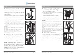
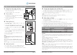
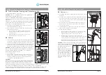
Mounting pole
Flowmeter
Air line
Oxygen line
Vapotherm
2000i
Delivery tube
Sterile
Water
Bag
Simple, easy
to use touch
control panel
and information
screen.
Vapor transfer
cartridge
Note: System specification
and front panel layout
may vary.
VSS-1
Spike set
Air/Oxygen
Blender
Section 4
Set-up
4.1
The 2000i Unit
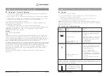
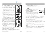
1. The back of the 2000i has an IV pole clamp that
enables IV pole attachment.
2. The unit should be mounted on a sturdy IV pole
approximately two feet from the top of the
pole to facilitate ease of access and proper
flow from sterile water system.
3. If using an oxygen blender, mount the blender
above the Vapotherm 2000i on the IV pole.
4. Connect blender hoses into both air and
oxygen wall connections.
5. Plug Vapotherm power cord into a hospital
wall power outlet.
WARNINGS:
Aseptic technique (including proper hand washing
and avoiding direct hand contact with connection
points) should always be followed when setting up
and operating the Vapotherm 2000i.
The medical gas source is external to the Vapotherm
2000i. Always verify the integrity of the medical gas
source and utilize bacterial filters if necessary.
Closed system components (VSS-1, Vapor Transfer
Cartridge and Patient Delivery Tube) should not be
opened in patient care area.
4.2
Selecting the Vapor Transfer
Cartridge
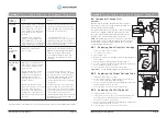
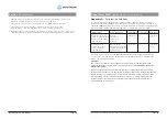
Vapotherm provides both a high flow cartridge
(VT01-AS) and a low flow cartridge (VT01-BS).
• The high flow cartridge (VT01-AS) should be
used with the pediatric cannula with an
operational flow range of 5 – 20 liters per minute
(lpm) or with adult sized cannula with an
operational flow range of 8– 40 lpm.
• The low flow cartridge (VT01-BS) should be
used with the neonatal, premature, infant, or
intermediate sized cannula with an operational
flow range of 1– 8 lpm.
WARNINGS:
Do not exceed maximum operational flow rates of 40 lpm
for the high flow cartridge (VT01-AS) and 8 lpm for the low flow cartridge (VT01-BS).
Ensure that the correct cartridge is inserted before operating.
Section 3
About the Vapotherm
®
2000i
The Vapotherm 2000i warms and humidifies flows of air, oxygen or medical gas blends for delivery to a
patient, by nasal cannula or Vapotherm approved interface.Warming and humidification of breathing gas
occurs in a Vapor Transfer Cartridge, where air and water are separated by a membrane permeable to
water vapor. The membrane consists of microtubules constructed of polysulfone material. The membrane
meets HIMA (Health Industry Manufacturers Association) standards on filters for sterilizing liquids and has
been shown to effectively exclude bacteria from crossing from the water circulation to the gas flow.
The warmed humidified gas stream reaches the patient via a patented triple lumen Patient Delivery Tube.
Humidified gas flow is delivered through the center lumen. The outer lumens contain water which is
warmed via an internal heater and propelled through the system via an internal pump (
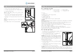
See schematic,
fig. 1).
This maintains breathing gas temperature and minimizes condensation. The final patient interface
is a Vapotherm nasal cannula or approved interface configured to minimize resistance and heat loss.
NOTE:
The water circuit and gas circuit of the Vapotherm 2000i do not come in contact with each other.
Respiratory gases are supplied to the Vapotherm™ 2000i from an external gas supply, typically through a
standard wall-mounted flow meter connected to the hospital medical gas supply. Gas flow rate is controlled
by the external flow meter or medical gas blender. There are no flow controls on the Vapotherm™ 2000i.
Connections for gas flow and water are made via the rear panel. All Vapotherm 2000i controls are on the
front panel of the device.
WARNING:
Use of patient interfaces not recommended by Vapotherm may cause safety concerns or
affect the performance of the device.
Operating Instruction Manual
Page 6
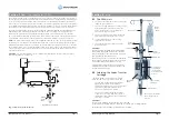
Fig. 1
Simplified System Diagram
Water Reservoir
Pump
Heater
Heated
Delivery
tube
Breathing Gas to Patient
Breathing Gas
Inlet
Vapor
Transfer
Cartridge


