background image


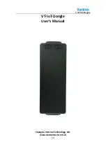
VT-IOT-Dongle   


12

21


3.3.1


CONNECTOR


 Connector

  2x5pin,2x2mm 


signal


connector


10 

RX1+ 
OR 
SPI_SCK 

RX1- 
OR 
SPI_D0

TX1+ 
OR 
SPI_D1 

TX1- 
OR 
SPI_CS

RS32_TX
OR 
RS485_B

RS232_RX
OR 
RS485_A 

GND 

GND 

VCC_5V

VCC_5V


The


mating


connector


reference


NSXD


S2008H

2X5P


The


connect


diagram


of


the


mating


connector:


Pin1 

Pin2 

Pin9 

Pin10 

Summary of Contents for VT-IoT-Dongle

Page 1: ...VT IOT Dongle 1 21 VT IoT Dongle User s Manual Chengdu Vantron Technology Ltd www vantrontech com cn ...

Page 2: ...VT IOT Dongle 2 21 Revision History No Version Description Date 1 V1 0 First release 2018 06 25 2 V1 1 Second release 2018 09 27 3 V1 2 Third release 2018 10 16 4 V1 3 Fourth release 2018 12 25 ...

Page 3: ...Instructions for Power Cables and Accessories 5 2 Overview 7 2 1 Introduction 8 3 VT IOT DONGLE Hardware Instructions 9 3 1 Product Appearance 9 3 2 Specifications 11 3 3 Interface Description 11 3 3 1 CONNECTOR 12 3 3 2 SIM CARD 13 3 3 3 USB TYPE C connector 14 3 3 4 BOOT SWITCH 14 3 3 5 SD CARD DEBUG Connector 15 3 3 6 SD CARD DEBUG board optional 15 3 3 7 Mounting hole 16 3 3 8 Operating instru...

Page 4: ...mation Vantron Technology Vantron E mail sales vantrontech com The trademarks and registered trademarks in this manual are properties of their respective owners No part of this manual may be copied reproduced translated or sold No changes or other purposes are permitted without the prior written consent of Vantron Vantron reserves the right of all publicly released copies of this manual 1 2 Notes ...

Page 5: ...danger of injury electric shock fire or any damage to the device 1 7 Precautions Pay attention to the product labels safety instructions printed on silk screens Do not try repairing this product unless declared in this manual Keep away from heat source such as heater heat dissipater or engine casing Do not insert other items into the slot if any of this device Keep the ventilation slot ventilated ...

Page 6: ...ng Instructions Please power off before cleaning the device Do not use spray detergent Clean with a damp cloth Do not try cleaning exposed electronic components unless with a dust collector Support for special fault Power off and contact technical support personnel of Vantron in case of the following faults The device is damaged The temperature is excessively high Fault is still not solved after t...

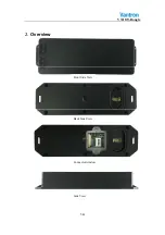
Page 7: ...VT IOT Dongle 7 21 2 Overview Front Side View Back Side View Connector window Side View ...

Page 8: ...ipped with the state of the art technology and the best product services Vantron s VT IOT DONGLE products are based on the most advanced ARM and Intel Atom processors and have low power consumption and high integration The products are designed for applications of VT IOT DONGLE in industrials medicals financial retail vehicle and transportations etc ...

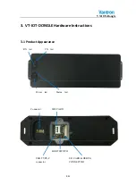
Page 9: ...VT IOT Dongle 9 21 3 VT IOT DONGLE Hardware Instructions 3 1 Product Appearance USB TYPE C connector Power led Status led RX led TX led Connector SIM CARD SD CARD DEBUG CONNECTOR BOOT SWITCH ...

Page 10: ...VT IOT Dongle 10 21 ...

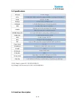
Page 11: ...On board WIFI 802 11 a b g n ac and Bluetooth 4 2 COM Port 1x RS232 485 select by GPIO LED Power Status RX TX RTC Support with Coin Battery OS Linux or XOS Optional support Python MQTT application Power Input DC 5V Dimension 152mm L x 48mm W x 24 2mm H Weight 120g Enclosure Black Plastic Box Protection IP67 Temperature Operating 10 55 Storage 20 70 ETR 40 85 Optional Humidity 5 95 RH at 25 35 Non ...

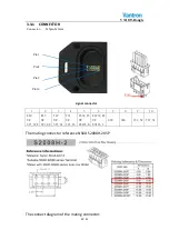
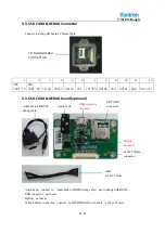
Page 12: ...al connector 1 2 3 4 5 6 7 8 9 10 RX1 OR SPI_SCK RX1 OR SPI_D0 TX1 OR SPI_D1 TX1 OR SPI_CS RS32_TX OR RS485_B RS232_RX OR RS485_A GND GND VCC_5V VCC_5V The mating connector reference NSXD S2008H 2X5P The connect diagram of the mating connector Pin1 Pin2 Pin9 Pin10 ...

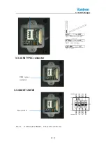
Page 13: ...VT IOT Dongle 13 21 The sample pictures 3 3 2 SIM CARD MICRO SIM CARD ...

Page 14: ...VT IOT Dongle 14 21 3 3 3 USB TYPE C connector 3 3 4 BOOT SWITCH Pin1 3 110 Boot from EMMC 001 boot from SD card USB type c connector Boot switch ...

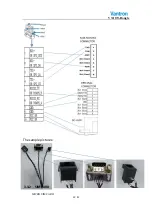
Page 15: ... Default 3 3 6 SD CARD DEBUG board optional Audio Jack connect to Audio Jack to DB9M debug cable use to debug with RS232 USB connector not used Button not used 1x12x1 25mm connector connect to IOT DOMGLE with cable 1x12x1 25mm SD CARD DEBUG CONNECTOR Audio Jack USB connector Not used SD CARD connector Button not used 1x12x1 25mm connector Audio Jack to DB9M debug cable cable 1x12x1 25mm ...

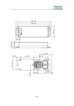
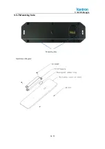
Page 16: ...VT IOT Dongle 16 21 3 3 7 Mounting hole Installation Diagram Mounting hole ...

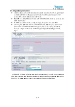
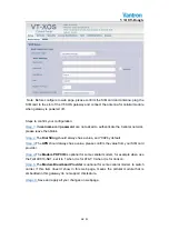
Page 17: ...es Wi Fi The default Wi Fi name is wifi_iot dongle the password is 12345678 Commonly the default IP address is 192 168 0 1 the default login username and password are admin admin The first login requires user to change the default username and password These modified login settings will affect login via web pages Cellular Set the APN input the user name and password of the SIM Card If the SIM Card...

Page 18: ...l String should always has a value and 99 by default Step 3 The APN should always has a value please confirm the value from your SIM card provider Step 4 The Modem PDP CID is optional for some cellular modem for example when use the Telit LE910 NA1 set it to 1 when it is for AT T 3 when it is for Verizon Step 5 The Modem Broadband Provider is optional for some cellular modem to switch carrier If t...

Page 19: ...itted to open the enclosure to adjust and replace the structure and components of the device Do not change components unless the power cord is removed In some cases the device may still have residual voltage even if the power cord is removed Therefore it is a must to remove and fully discharge the device before contact so as to avoid injury Unauthorized changes to this product or its components ar...

Page 20: ...orm For a Class B digital device or peripheral the instructions furnished the user shall include the following or similar statement placed in a prominent location in the text of the manual NOTE This equipment has been tested and found to comply with the limits for a Class B digital device pursuant to Part 15 of the FCC Rules These limits are designed to provide reasonable protection against harmfu...

Page 21: ...e 300 Pleasanton CA 94566 Tel 1 916 202 7042 Email sales vantrontech com China Office Chengdu Vantron Technology Ltd Address 6rd floor 1rd building No 9 3rd WuKe East Street WuHou District Chengdu P R China 610045 Tel 86 28 8512 3930 3931 8515 7572 6320 Email sales vantrontech com cn ...

Reviews: