PAGE 2
PRINTED IN THE U.S.A.
ASSEMBLY, LEG INSTALLATION
SECTION 2
MAXIMUM CAPACITY (SCFM)
Rated capacities are based on the following conditions: Inlet and approach temperature at inlet pressures 80 to 125 PSIG.
Approach Temperature:
The number of degrees above the temperature of the cooling medium (in this case ambient air) to
which the aftercooler reduces the compressed air. A higher approach does
not
mean better performance.
INLET TEMP.
APPROACH
TEMP.
O
F
MODEL
AC-140
AC-150
AC-160
AC-170
AC-180
AC-190
AC-200
AC-210
AC-220
15
520
890
1178
1475
1950
2420
3000
3580
4140
20
605
1025
1360
1710
2260
2800
3470
4120
4800
5
175
308
415
520
710
870
1090
1295
1530
10
375
560
754
950
1290
1580
1980
2360
2785
15
430
760
1020
1290
1720
2140
2680
3200
3760
20
500
880
1180
1460
1950
2460
3100
3710
4320
5
160
290
390
490
660
820
1035
1243
1460
10
300
545
712
900
1200
1490
1880
2260
2660
15
400
725
950
1200
1600
2000
2500
3000
3500
20
464
840
1100
1380
1860
2300
2870
3450
4015
10
250
450
588
735
965
1210
1426
1794
2090
15
340
605
785
980
1290
1595
1980
2360
2760
20
396
701
910
1130
1480
1840
2270
2715
3200
5
125
225
280
355
460
572
705
840
950
10
235
410
520
650
840
1040
1290
1530
1740
15
305
540
690
865
1135
1400
1725
2040
2350
150
O
F
200
O
F
350
O
F
250
O
F
300
O
F
MAXIMUM PRESSURE DROP LESS THAN 3 PSI.
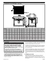
2.1 INSTALLING THE LEGS
This unit was shipped without the legs installed.
The legs should be installed before placing the
aftercooler in the piping system. Carefully lift and
support the unit several feet from the floor.
Position the legs against the unit and fasten them
in place using the fasteners provided. Make sure
the fasteners are tightened in place.
FIGURE 1 LEG INSTALLATION DETAIL
SPECIFICATIONS AND DIMENSIONS
SECTION 3
3.1 SPECIFICATIONS
WEIGHT
AC-140 ........ 120 LBS
AC-190 ........... 600 LBS
AC-150 ........ 170 LBS
AC-200 ........... 625 LBS
AC-160 ........ 330 LBS
AC-210 ........... 645 LBS
AC-170 ........ 450 LBS
AC-220 ........... 750 LBS
AC-180 ........ 515 LBS
DIMENSIONS .............. See Section 3.2
INLET/OUTLET CONNECTIONS
AC-140 ............ 2" NPT (F)
AC-190 ............... 4" NPT (F)
AC-150 ............ 2" NPT (F)
AC-200 ............... 4" NPT (F)
AC-160 ............ 3" NPT (F)
AC-210 ............... 4" NPT (F)
AC-170 ............ 3" NPT (F)
AC-220 .............. 4" NPT (F)
AC-180 ............ 3" NPT (F)
MAXIMUM WORKING PRESSURE
ALL MODELS .................. 250 PSIG
MAXIMUM WORKING TEMPERATURE
ALL MODELS .................. 350
O
F
MATERIALS OF CONSTRUCTION
CABINET ......................... Steel with baked enamel finish
FAN GUARD ................... Steelwith baked enamel finish
FAN ................................. Polypropylene blades with aluminum hub
CORE .............................. Aluminum
MOTOR ........................... TEFC
MOTOR SPECIFICATIONS AND DATA
See Wiring Diagram, Figure 5 on page 6.
FAN DATA
(AMBIENT AIR FLOW)
AC-140-6 ......................... 2200 SCFM
AC-140-7 ......................... 230V, 1825 SCFM 460V, 2200 SCFM
AC-150-6 ......................... 3600 SCFM
AC-150-7 ......................... 230V, 3025 SCFM 460V, 3600 SCFM
AC-160-6 ......................... 4700 SCFM
AC-160-7 ......................... 4700 SCFM
AC-170-6 ......................... 7000 SCFM
AC-170-7 ......................... 7000 SCFM
AC-180-7 ......................... 9700 SCFM
AC-190-7 ......................... 11000 SCFM
AC-200-7 ......................... 14000 SCFM
AC-210-7 ......................... 17500 SCFM
AC-220-7 ......................... 17500 SCFM
AC-140-6 thru AC-160-6 ...... 115/230-1-60
AC-170-3 ............................... 230-1-60
AC-140-7 thru AC-220-7 ...... 230/460-3-60
ELECTRICAL REQUIREMENTS
10
384
650
871
1090
1440
1790
2220
2650
3064
20
355
625
780
990
1300
1610
1980
2350
2700
5
135
245
320
405
530
660
784
985
1150
5
210
355
480
600
790
980
1220
1450
1680


