background image

6

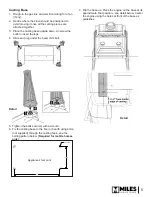
Casting Side Panels

1.  On the casting side panels, release the top and 

bottom screws.

2.  Drop a hinge pin on the back corner of base and 

drop the side panel on the pin.

3.  Rotate the panel towards the engine.

4.  Repeat with the other casting side panel.

Fixing Casting Side Panels & Engine

1.  Adjust the position of the engine to locate the top 

and bottom screws of the side panels into the 
slots of the engine’s side bracket. Tighten the top 
and bottom screws.

2.  Adjust the engine as required and fi x it to the 

casting base at bottom of its side brackets with the 
nuts and bolts provided.

Top Spar

1.  Position the top spar on the side brackets located 

between the engine and the cast sides.

2.  Fix the spar with two 3/8” pre-assembled screws 

provided.

Complete engine installation

Refer to the engine installation manual for the following 
steps.
1.  Reposition the lighting instructions plate, remote 

control receiver and connect gas line to the inlet 
pipe.

2.  Install the fan, if used, and convert the top outlet to 

a rear outlet or co-linear outlet if necessary.

3.  Install venting system.

4.  Connect the gas and install the logs.

5. Refi t the window and the hot glass warning plate.

6.  Set up the remote control and check operation.

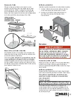
Front Installation

Hook the cast front to the side brackets located 
between the engine 
and the cast sides.

Cast front

Hook

Details

Engine

Side bracket

2

3

Summary of Contents for MADRONA MFCS01

Page 1: ...e listed heater models The application of this kit does not affect the venting capa bilities or method of preparation of the MF28 heater as de scribed in the MF28 heater installation manual To complet...

Page 2: ...anel Arched front panel Arched barrier screen Fret traditional MFCS01 3 black Base panel Square front panel with square barrier screen MFCS02 1 majolica Infill plate Top panel Legs 4 RH side panel LH...

Page 3: ...5 8 venting Suggested gas line access point through wall Route to avoid optional fan Pipe supplied with engine see engine manual p 18 x Mantel shelf clearances Mantel Depth A 0 1 0 26 mm 2 5 51 127 m...

Page 4: ...E ON ITS PACKAGING BASE to avoid damage to the control valve wires and pipes until ready to insert into stove casing Casting Tolerances Due to the nature of cast iron and concrete dimen sional consist...

Page 5: ...down Unscrew the bolts to insert the legs 4 Slide each leg under the head of its bolt 5 Tighten the bolts securely with a wrench 6 Fix the casting base to the floor or hearth using bolts not supplied...

Page 6: ...op Spar 1 Position the top spar on the side brackets located between the engine and the cast sides 2 Fix the spar with two 3 8 pre assembled screws provided Complete engine installation Refer to the e...

Page 7: ...hout removing the front casting Once the stove has cooled down and with extra care not to hit the glass of the window simply slide up the fret out of its brackets angle it up and remove it To put it b...

Page 8: ...8 9 10 Description Part no Description Part no Black Majolica Black Majolica 1 Base 4000926AH 4000926MJ 8 Infill Plate 4000927AH 4000927MJ 2 Top Panel 4000928AH 4000928MJ 9 Hook 2 4000990 with 400883...

Page 9: ...rni avec ce foyer r duit le risque de br lure en cas de contact accidentel avec la vitre chaude et doit tre install pour la protection des enfants et des personnes risques DANGER INSTALLATEUR Laissez...

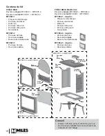
Page 10: ...1 3 Panneau de base Devanture carr e MFCS01 1 ou MFCS02 1 MFCS01 2 ou MFCS02 2 MFCS01 3 ou MFCS02 3 Crochets Devanture carr e Base de feu Panneau du dessus Plaque de remplissage Base Pattes Panneau c...

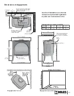
Page 11: ...d acc s la conduite de gaz sugg r Orientez pour viter le ventilateur facultatif Tuyau fourni avec le foyer voir guide du foyer p 18 D gagements pour manteau ou tablette Profon deur A 0 1 0 26 mm 2 5...

Page 12: ...itaires peuvent avec le temps se d colorer se d former ou craquer S lectionnez les mat riaux avec soin et consultez votre marchand au besoin Installation D ballez l appareil et le casier de fonte Le f...

Page 13: ...ns rer les pattes 4 Glissez chaque patte sous la t te de son boulon 5 Resserrez les boulons l aide d une cl 6 Remettez la base l endroit Fixez la base de fonte par les pattes au plancher l aide de bou...

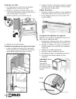
Page 14: ...dessus 1 Positionez la plaque du dessus sur les supports de c t s situ s entre le moteur et les c t s de fonte 2 Fixez la plaque du dessus avec deux vis de 3 8 pr assembl es Completez l installation d...

Page 15: ...de feu en fonte amovible Pour faciliter l acc s la soupape et au r cepteur de t l commande la base de feu peut tre enlev e sans avoir d crocher la devanture Une fois le po le refroidi et en prenant b...

Page 16: ...000926AH 4000926MJ 2 Dessus en fonte 4000928AH 4000928MJ 3 Pattes 4 4000929AH 4000929MJ 4 Panneau c t droit 4000930AH 4000930MJ 5 Devanture arqu e 4000934AH 4000934MJ 6 Base de feu 4000935AH 4000935MJ...

Reviews: