3
B
A
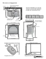
Mantel
23”
(584 mm)
7-1/2”
(191 mm)
25-1/8”
(638 mm)
27-1/2” (699 mm)
14”
(356 mm)
17-7/8”
(454 mm)
Ø 6-5/8”
venting
Supplied with
top vent; field
convertible to
rear vent
Centre of vent
28-1/2 ” (724 mm)
x
Gas inlet position
3/8” fem. NPT
x
2”
(52 mm)
minimum
Gas line connection point
3/8” NPT FEMALE at valve
Sidewall
17-7/8”
(454 mm)
4”
(102 mm)
2” (52 mm)
minimum
Ø 6-5/8”
venting
Suggested gas line
access point through wall.
Route to avoid optional fan.
Pipe supplied with
engine (see engine
manual p. 18)
x
Mantel / shelf clearances
Mantel
Depth ‘A’
0–1”
(0–26 mm)
2–5”
(51–127 mm)
6–18”
(152–457 mm)
19–24”
(483–610 mm)
Mantel
Height ‘B’
34”
(864 mm)
36”
(914 mm)
38”
(965 mm)
42”
(1067 mm)
Corner clearances
Min. 2”
between
combustible
wall and
stove
Min. 2” between
combustible wall
and stove
32-1/2” minimum
42” minimum
26” maximum
Alcove clearances
Dimensions & Clearances
For installation purposes, diagrams
represented by the arched front


