background image

33

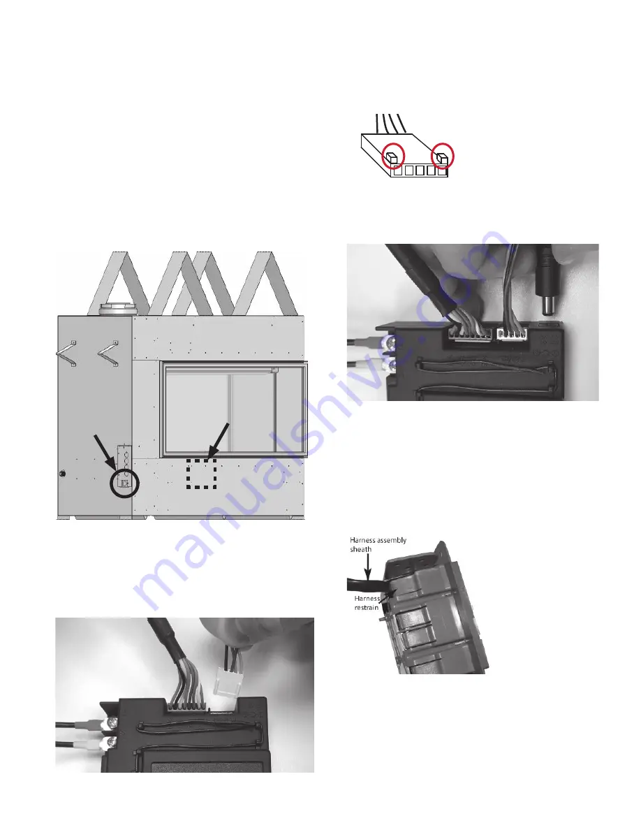
Installing Wall Switch Kit

A remote battery wall switch kit is provided with this 

appliance. It is connected to the receiver in the 

fi

 replace. 

The receiver is located under the bottom plate.
1.  Decide where the switch is to be installed in the wall. 

Do not locate the switch within the non-combustible 

zone above the 

fi

 replace. 

2.  Thread the harness through the access hole in the 

appliance, located below the electrical junction box. 

DO NOT run the wire over top of the appliance.

3.  Pull out the receiver. You can remove the ignition 

wire to improve access.

4.  Take the signal wire and plug it into the receiver’s 

connection slot as indicated (the other slot should 

already be 

fi

 tted with the valve’s wire harness 

connector)

!

IMPORTANT: The connection 

can only be done one way. 

Do not force it or damage 

the pins on the receiver box!

5.  Connect the 6 volt power wire to the receiver.

6.  On the outside of the 

fi

 replace, run the harness to 

the junction box location. Use insulated type staples 

to secure the wiring to framing.

7.  Feed the harness assembly through a restraint on 

the rear of the junction box, feeding through until 

the harness sheath is pinched by the retainer. Ensure 

there is su

  cient wire length inside the junction box 

to make connection to the switch plate and battery 

holder.

8.  Secure the junction box to the mounting surface 

using appropriate fasteners (not supplied).

Entry

Receiver location

Installation

Wall Switch Kit

Summary of Contents for LX1 Series

Page 1: ...he gas supplier s instructions If you cannot reach your gas supplier call the fire department Installation and service must be performed by a qualified installer service agency or the gas supplier Hot...

Page 2: ...h Vancouver BC Canada V7H 3B1 T 604 984 3496 F 604 984 0246 valorfireplaces com This appliance may be installed in an after market permanently located manufactured mobile home where not prohibited by...

Page 3: ...ation Location 23 Vertical Vent Termination 24 Co linear Venting 25 Appliance Preparation 26 Unpacking the Fireplace 26 Installing Handles 27 Installing Stando s 28 Installation 29 Installing Electric...

Page 4: ...led Some materials or items although safe may discolor shrink warp crack peel and so on because of the heat produced by the fireplace Avoid placing candles paint ings photos and other combustible obje...

Page 5: ...assembly must be vented directly to the outside and must never be attached to a chimney serving a separate solid fuel burning ap pliance Each gas appliance must use a separate vent system Common vent...

Page 6: ...1 370 m in Canada please consult provincial and or local authorities having jurisdiction Model 2100PKN 2100PKP Gas Natural Propane Altitude Ft 0 4 500 feet Input Maximum Btu h 25 000 25 000 Input Min...

Page 7: ...s may be cut to required length Gas Conversion Kits 2100NGK Natural Gas Conversion Kit 2100PGK Propane Gas Conversion Kit Other Accessories 1270RBK Remote Blower Kit requires use of HeatShift LDK4 kit...

Page 8: ...LQVWDOODWLRQ on this side only Center of vent 17 432 mm 8 203 mm 11 1 4 286 mm 11 279 mm 18 1 2 470 mm 9 1 4 235 mm 18 1 2 470 mm 9 1 4 235 mm 47 1 4 1200 mm 36 915 mm 46 3 4 1187 mm Window 31 1 8 791...

Page 9: ...ly A liner packed separately Remote Battery and Wall Switch Kit HeatShift duct kit mandatory packed separately Gas conversion kit if necessary Venting accessories Electrical accessories 5 Carefully re...

Page 10: ...ve ce ment board Wood base below fireplace 2100P heater Mandatory HeatShift Plenum or Duct Termination plates top HeatShift system ordered separately See also Overview HeatShift Canopy on page 12 for...

Page 11: ...P heater The easiest way to frame a ceiling height installation the Steel Framing Kit 2100SFK allows installers to quickly and easily install a complete framing option purpose built and size for the 2...

Page 12: ...allation Manual for this kit for more details HeatShift canopy collects and redirects hot convected air to the side into two 5 pipes Top HeatShift discharge min 2 1 2 clearance below ceiling Combustib...

Page 13: ...LVK KHUH VHSDUDWLQJ FDYLW IURP combustible projections 2QO QRQ FRPEXVWLEOH material in contact with the appliance above ERWWRP HGJH RI RSHQLQJ RPEXVWLEOH QLVKLQJ PDWHULDOV up to PP WKLFNQHVV DOORZHG E...

Page 14: ...s to Combustibles on page 13 Max 1 1 4 32 mm thickness combustible wall finish allowed if within 4 of opening Combustible framing material allowed Zero clearance stand o s 2 front 2 rear HeatShift pip...

Page 15: ...ial allowed HeatShift plenum or duct plates framing required top front or rear See Appendix D in this manual WARNING Ensure weight of wall above is NOT carried by the appliance 9 5 8 245 mm Combustibl...

Page 16: ...ength at this height 4x6 5 8 elbow directly on the appliance Minimum Vertical Vent Below is the minimum vent height when the elbow is placed directly on the appliance collar If calculating the vent he...

Page 17: ...Finishes The HeatShift Duct Kit reduces the wall temperatures and minimizes the possibility of cracking wall finishes If a clean finish with no tile etc is desired joints in the cement board and the t...

Page 18: ...ee the diagrams at right for dimensional details of these restricted areas WARNING DO NOT SCREW OR DRILL in the areas marked in the diagrams at right Electric shock and or explosion risk present WARNI...

Page 19: ...rizontal run of vent pipe allowed for the particular installation Tape all joints including all elbow joints Framing Vent in Combustible Walls Ceilings When penetrating through combustible walls and c...

Page 20: ...mended components Sidewall Vent Roof Vent PIPE LENGTH IF REQUIRED 90 ELBOW PIPE LENGTH 2 PIECE WALL THIMBLE HORIZONTAL TERMINATION VERTICAL TERMINATION STORM COLLAR FLASHING ATTIC INSULATION SHIELD AT...

Page 21: ...horizontal pipe runs must be graded 1 4 inch per foot upwards in the direction of the exhaust flow The final pipe length when terminating through the wall may be graded downwards slightly to prevent w...

Page 22: ...length of the vent pipe The fireplace is installed with the restrictor in the roof of the firebox at the exhaust exit above the firebox ba e To access the restrictor 1 Remove the ba e 10 screws five o...

Page 23: ...he terminal 36 90 I Clearance to service regulator vent outlet 36 90 J Clearance to non mechanical air supply inlet to the building or the combustion air inlet to any other appliance 12 30 K Clearance...

Page 24: ...vented soffit Min 36 vented soffit Termination cap Min 18 Storm collar Roof flashing H Vertical Vent Termination Venting Co axial Termination Roof Pitch Minimum H feet Flat to 7 12 1 Over 7 12 to 8 12...

Page 25: ...and 13 respectively Fit the liners to the co linear adapter paying attention to inlet and exhaust as well as the minimum liner bend radius Rules for Co Linear Venting Min 10 max 40 vertical pipe Max...

Page 26: ...pliance and discard 2 Unpack any loose items from around the appliance 3 Verify that you have all the components required for the installation including approved non combustible cement board liners an...

Page 27: ...s for installation is attached to one of the handles Remove handles and the bag and save the screws 3 Fasten handle on the wall end with six screws 4 On the other end of the unit fasten the other hand...

Page 28: ...ando has three perforated lines on it Fold along the perforations to create a triangular shape Fold x3 Appliance Preparation Once all four stando s are folded up screw each one down at its remaining c...

Page 29: ...ments The included V Module power supply includes a three prong grounded plug to plug into a grounded receptacle also included with the fireplace The receptacle needs to be wired up within the firepla...

Page 30: ...dy plugged in V module location attached inside panel Accessing Junction Box After Finishing To access the electrical junction box after wall finishing is complete and the fireplace is operational you...

Page 31: ...as lines should be of ground joint type The gas supply line must be sized and installed to pro vide a supply of gas su cient to meet the maximum de mand of the appliance without undue loss of pressure...

Page 32: ...nnections must be tested for leaks after installation or servicing All leaks must be corrected im mediately When testing for leaks Make sure that the appliance is turned o Open the manual shut o valve...

Page 33: ...nection slot as indicated the other slot should already be fitted with the valve s wire harness connector IMPORTANT The connection can only be done one way Do not force it or damage the pins on the re...

Page 34: ...suit the homeowner s wishes 11 Locate and secure the magnet plates using 2 long screws provided 12 Place and secure the cover plate to the box using 4 screws provided 13 Feed the cable tie through th...

Page 35: ...p Otherwise the installer can complete the physical installation and leave the remaining setup instructions for the homeowner Physical Installation The WiFi module must be wired into a compatible rece...

Page 36: ...in the roof of the fireplace and slide the bracket away from the wall 2 Insert the top of the liner the thinner end in the gap between the wall and the retaining bracket 3 Swing the bottom of the line...

Page 37: ...2 Slide the liner in from either side between the wall and the light rail and retaining bracket 3 Slide the retaining bracket against the liner and tighten the screw 4 Fold the bottom clip along its p...

Page 38: ...dicate holes for support placement Installation Carefully unpack the kit Note the logs have numbers pressed into their undersides Install the logs as follows 1 Place 2 supports over the holes indicate...

Page 39: ...an deposit fine dust in the burner ports You may not need to use all the em bers supplied Be careful not to block any burner ports 10 Be sure to keep the pilot light safe zone clear of all embers This...

Page 40: ...kit Note some logs have pins and holes to help you place them on the burner platform or other logs Install the kit as follows 2965 3720 2939 2967 2966 1 Place the vermiculite onto the burner by hand...

Page 41: ...720 Leave the other end of log 2939 across the media tray 8 The arrangement should now look like this 9 Add the remaining vermiculite around the media tray You may not need to use the entire bag 10 Pl...

Page 42: ...dust in the burner ports Be careful not to completely block any burner ports You may not need to use the entire ember mix 3 Ensure the pilot light safe zone is not blocked by embers This is important...

Page 43: ...43 7 Repeat on the right hand side of the fireplace 8 The completed arrangement will look like the one below Note some minor adjustments may be needed to improve flame picture Installation Fuel Beds...

Page 44: ...4 ceramic pads evenly on the media tray surrounding the burner 2 Place glass covers 6857 and 6858 onto the ceramic pads as shown Note the cutout in 6857 that fits around the pilot light Installation 3...

Page 45: ...onfirming the pairing is done 5 If you hear one long beep the pairing sequence has failed or the wiring is incorrect This is a one time pairing only and is not required when changing the batteries of...

Page 46: ...are provided with the kit Cover the screws with the included caps to finish the mounting Once mounted the holder is magnetic simply place the remote gently into the holder IMPORTANT The location of th...

Page 47: ...ebox See Remove the Windows on page 26 for details on removing the windows from the fireplace It is easiest to see and change the light bulbs opposite the window you are opening You may find it easier...

Page 48: ...rly on the top and sides ENSURE THE FRONT WINDOWS SILICONE GASKETS ARE WELL SEALED FROM TOP TO BOTTOM TO THE SIDE WIN DOWS 10 Replace the hot glass warn ing plate against one of the side windows in th...

Page 49: ...lations Depending of the fuel bed used altitude and other considerations the flame picture may be improved by adjusting the aeration The need for adjustment should be determined only by operating the...

Page 50: ...e them Installation Installing Plates and Barrier Screens Installing Plates For safety install all plates top and bottom as supplied with the fireplace if they have been removed The top and vertical p...

Page 51: ...y Holder PILOT Wifi Module optional V Module 120V Low voltage AC Power Lights MAN Knob Combination Control Valve Main Valve Knob PANEL red yellow Receiver Antenna RESET Button RBWSK Connector Battery...

Page 52: ...33 Co linear to Co axial Adapter 46DVA GK 46DVA CLTA TM 4CTA 4DCAT33 DV to B Vent Adapter Aluminum Flexible Liner 3 diameter NOTE 2 ply liner approved to CAN ULC S635 suitable for venting gas applianc...

Page 53: ...oof Flashing 46DVA FF TF 4F SV4F 949606001 Masonry Flashing TF 4MF 559FSK New Siding Flashing 658NSFK Various Venting System Parts Wall Thimble 46DVA WT 4DT WT TM 4WT SV4RSM 4DWT 949064U Storm Collar...

Page 54: ...xt adjacent floor level b In the event that the requirements of this subdivision can not be met at the time of completion of installation the owner shall have a period of thirty 30 days to comply with...

Page 55: ...side wall horizontally vented gas fueled equipment does not provide the parts for venting the flue gases but identifies special venting systems the following requirements shall be satisfied by the man...

Page 56: ...lder 4004459 68 Handset Symax 10 button 4007548 69 GV60 valve repair kit not included 4004544 Description Part Number 1 Barrier screen front rear 2 4006979 2 Barrier screen end 4006865 3 Window assemb...

Page 57: ...87 Bag of splinters 4005813 Description Part Number 88 Driftwood log kit 2100DWK 89 Driftwood log 2965 4002965 90 Driftwood log 2967 4002967 91 Driftwood log 3720 4003720 92 Driftwood log 2939 4002939...

Page 58: ...1 2 3 2 3 4 5 4 6 4 6 4 7 8 9 10 11 12 13 14 15 16 17 18 19 20 2 21 22 23 24 26 25 27 28 29 35 36 37 2 37 2 38 39 40 41 2 41 2 42 2 42 2 43 44 45 46 47 48 50 49 52 53 54 55 51 56 57 58 59 60 61 62 63...

Page 59: ...pare Parts 70 71 2100RGP 2200LMP 2200FBP 72 2100DGM 73 74 75 76 2965 3720 2939 2967 2966 77 78 79 80 81 82 83 84 85 2 2100BLK 2100DWK 2100RSS 88 89 90 91 92 93 94 95 100 101 103 103 102 104 105 110 86...

Page 60: ...CORDANCE WITH LOCAL CODES IF ANY IF NONE FOLLOW THE NATIONAL FUEL GAS CODE ANSI Z 233 1 OR CANADIAN INSTALLATION CODES CAN CGA B149 AUTOMATIC SHUT OFF using the remote control handset D UH RU H SORVLR...

Page 61: ...n On Fire One Button lighting default Two Button lighting simultaneously Press and hold for 4 seconds until 8 short beeps and a blinking series of lines confirms the start sequence has begun Release b...

Page 62: ...ns 1 Install batteries All icons are displayed and flashing 2 While the icons are flashing press the relevant func tion button and hold for 10 seconds 3 The function icon will flash until deactivation...

Page 63: ...ostatic and Eco modes Maximum countdown time is 9 hours and 50 minutes Light Dimmer Operation On Press is displayed Light is on at preset level Off Press disappears Light turns o Setting 1 Press and h...

Page 64: ...l Mode The on o status of the fireplace as well as flame height are manually controlled by the user PM ON OFF PM PM Thermostatic Mode On Press is displayed Preset temperature displays briefly followed...

Page 65: ...ing PROGRAM 1 1 1 OFF are displayed ALL is displayed briefly Hour flashes 2 To select hour press or 3 To confirm press 1 OFF are displayed ALL displayed briefly Minutes flash 4 To select minutes press...

Page 66: ...es CAUTION Do not use a screwdriver or other metallic object to remove the batteries from the battery holder or the handset This could cause a short circuit Low Battery Receiver With low battery power...

Page 67: ...o pilot flame No gas supply Air in pilot supply line No spark Reversed polarity in thermocouple wiring Incorrect pilot orifice if valve has been converted from LPG to NG or vice versa F07 Low battery...

Page 68: ...rease flame height Press and hold small flame button to gradually decrease flame height Using the Wall Switch The Wall Switch can be used to control the fireplace You can turn the pilot on or o and yo...

Page 69: ...evisions artwork etc Only the HeatShift kits listed below may be used with the LX1 5 inch diameter duct used with this kit must be metal and meet requirements of UL 181 Class 1 Air Duct Flexible alumi...

Page 70: ...70 Appendix D HeatShift 2100HSC Kit Contents 2100HSC Takeo collars not required Qty 2 2x4 cut to planned height required not included...

Page 71: ...x 6 LDK6 2 10 x 5 aluminum flex LDK5 supplied separately 38 frame white 2 14 x 6 grilles included white 4 5 take off collars included LDK Kits Contents 39 5 8 1007 mm 15 3 4 400 mm LDK7 2 Duct termina...

Page 72: ...ects in front of or on top of air outlet s AVOID locating outlet within 7 feet of the floor level as discharge air temperatures are hot D O N O T D I S C H A R G E T H R O U G H E X T E R I O R W A L...

Page 73: ...through ceiling Cement board or similar non combustible finish Combustible finish allowed below opening see Installation Manual for details 14 356 mm Min 34 7 16 875 mm Installer may separate top duct...

Page 74: ...gid 5 UL 181 Class 1 Air Duct 4 Use LDK 6 kit or equivalent Min 1 clearance to combustibles around pipes Ceiling 11 279 mm 17 432 mm 8 203 mm 36 914 mm Min 30 Max 12 0 See table for offsets Min 2 1 2...

Page 75: ...fireplace when using LDK7 11 279 mm 17 432 mm 8 203 mm 36 914 mm Ceiling Min 30 Max 12 0 See table for offsets Min 2 1 2 opening required at ceiling Min 14 356 mm Flexible or rigid 5 UL 181 Class 1 Ai...

Page 76: ...Min 30 Max 12 0 Maximum allowable Horizontal Offset X offset for take off that s furthest away Ceiling LDK 3 or LDK 4 Min bend radius Top of fireplace Min 1 clearance to combustibles around pipes Supp...

Page 77: ...ndoffs 6 knock out each end for optional 1270RBK connection 11 1 2 8 4 1 2 wallboard mounting bracket and 1 1 2 standoff mounting bracket and 1 2 standoff Right Side View LDK 3 14 C L 7 6 5 dia collar...

Page 78: ...ons 5 dia collars 4 C L 7 4 1 2 9 3 4 9 3 4 4 1 2 19 1 2 2 1 2 13 1 2 16 19 1 2 9 3 4 9 3 4 Stand offs fold down for shipping Warning Label Stand offs Front View Top View Right Side View Perimeter of...

Page 79: ...Opening Rough Frame Opening See Installation Manual packed with appliance for minimum combustible cavity dimensions Note Min cavity dimensions may be dictated by LDK plenum when installing across corn...

Page 80: ...in 2 1 2 clearance to ceiling 1 2 5 1 2 min clearance to combustibles rear sides 1 min clearance to combustibles all around pipes 1 x 4 on edge to support plenum Maintain 1 clearance between pipes and...

Page 81: ...clearance around pipes 2 x 4 on edge to support plates as necessary maintain 1 clearance to pipes Wall finish required to form plenum above duct termination plates LDK 7 Duct Termination Plates 2 for...

Page 82: ...9 1 2 16 13 1 2 4 4 Stand off Non combustible zone above plates Perimeter of plates may be trimmed to suit installation Combustible framing allowed below plates 5 dia pipes maintain 1 clearance to com...

Page 83: ...ch of the collars and secure it with gear clamps provided DO NOT SPLICE DUCTS 6 Attach the top of the pipe sections to the plenum securing them with the gear clamps provided An upward slope must be ma...

Page 84: ...lope must be maintained in horizontal sections of pipes for proper convection Use straps as necessary to maintain the pipes posi tions Support horizontal sections every 24 inches 7 Continue with the f...

Reviews: