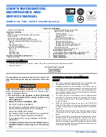
background image


MANTLE DEPTH “A”


1” 

2” 

3” 

4” 

5” 

6” 

7” 

CLEARANCE FROM BASE OF 
HEATER “B

”  

37 7/8” 

39 7/8” 

40 7/8” 

42 7/8” 

44 7/8” 

46 7/8” 

48 7/8” 

 
 Fig. 1b Clearances to combustible materials in front of enclosure opening - All installations 


  Fig 1d Combustible material enclosure -  For installations 
in Canada with unprotected combustible floor


Fig 1c Combustible material enclosure -  For installations in 

USA with protected combustible floor


6

Summary of Contents for 737AN

Page 1: ...GAS Open windows Extinguish any open flame Do not try to light any appliance Do not touch any electrical switch do not use any phone in your building Immediately call your gas supplier from a neighbo...

Page 2: ...llation 8 Pre installation preparation 8 Installing to fireplace 10 Installing gas supply 11 Assembling fuel bed 12 Control operation check 15 Pressure checks 15 Aeration adjustment 15 Facia outer sur...

Page 3: ...to the room construction in the vicinity of the appliance after installation e g additional mantle etc make sure that the changes conform to the installation requirements in this manual Never attempt...

Page 4: ...included with the kit 1 1 4 770ZCK Zero clearance kit Allows the furnace to be installed into an enclosure constructed of combustible material The kit must be used in this form of enclosure Enclosure...

Page 5: ...at the back that may need to be filled in In the USA it is mandatory that a hard surfaced non combustible hearth area must be maintained at least 16 in front of the fireplace This may be finished in...

Page 6: ...8 48 7 8 Fig 1b Clearances to combustible materials in front of enclosure opening All installations Fig 1d Combustible material enclosure For installations in Canada with unprotected combustible floo...

Page 7: ...use with natural gas only Model 737AP is for use with propane only The supply pressure must be between the limits shown in section 1 4 of this manual The supply connection is 3 8 NPT The supply gas fe...

Page 8: ...washers for outer surround fixing or 778FSK 2 Contoured black trim contains 1 Outer surround top channel black 1 Outer surround left side channel black 1 Outer surround right side channel black 2 Corn...

Page 9: ...the vent connection unit from the top of the appliance case by removing the screw at front Slide the vent connection unit back and lift clear see fig 5 Lift off Bottom Louver Unit Remove 4 screws Fig...

Page 10: ...plate using the two thread cutting screws supplied See figure 8 5 2 INSTALL TO FIREPLACE 5 2 1 Secure the collar on the vent connector unit to the 3 diameter chimney liner Fig 9 5 2 2 Slide the fire u...

Page 11: ...lied lightly to male threads to ensure excess sealant does not enter gas lines The supply line should include a manual shut off valve and union in the line to allow the appliance to be disconnected fo...

Page 12: ...handed Rest the bottom edges of the side walls on the firebox side supports Locate the top edges of the side walls in the gaps between the edges of the top heat baffle and the firebox sides Slide the...

Page 13: ...ter angled support and their outside ends should be under the cut outs at the front of the side walls fig 14 5 4 5 Install the side base bricks These bricks are left and right handed Place the side ba...

Page 14: ...front log and the right side base brick There should be no gap at the left side fig 16 5 4 7 Install the left cross log fig 17 The underside of the log is marked L for left and F for front Place the...

Page 15: ...on the thermostat unit see fig 10 The pressure check should be made with the appliance burning the valve control set at MAX and the thermostat control turned to HI Fig 18 Right cross log location Pres...

Page 16: ...uter facia to the front frame with the four nuts bolts and washers supplied fig 21 5 9 2 With 778FSK or 779FSK 2 contoured trim 5 9 2 1 Assemble the left and right side channels to the top channel usi...

Page 17: ...n the opening in the frame side 5 10 3 Locate the hooks on the inner front unit into the slots at each side of the fire box Push the inner front fully downwards fig 26 Fig 26 Inner front unit attachme...

Page 18: ...t and near the center This will prevent the convection air from interfering with the test Insert the match into one of the slots near the center Fig 29 The installation is satisfactory if the smoke is...

Page 19: ...e fuel pieces will show areas of charcoal gray color as would real burning logs 6 2 LIGHTING IF SPARK IGNITER FAILS In the unlikely event of failure to create an ignition spark using the control knob...

Page 20: ...ot be turned from ignition to off unless it is pushed in partially Do not force 4 Wait five 5 minutes to clear out any gas If you then smell any gas STOP Follow B in the safety information above If yo...

Page 21: ...line and other flammable vapors and liquids 6 4 3 Keep the area in front at the bottom of the appliance clear Obstructions will impede the flow of air to the appliance and cause incorrect combustion 6...

Page 22: ...ebox and carefully store 7 2 4 Remove the front frame as described in installation instructions section 5 1 4 7 2 5 Disconnect the gas supply line elbow at the appliance inlet pipe union 7 2 6 Disconn...

Page 23: ...Manufactured by HEATING BIRMINGHAM ENGLAND Because our policy is one of constant development and improvement details may vary slightly from those given in this publication Valor Ltd 1995 1997 23...

Reviews: