


BCs160VA
Nov. 15, 1997
SMART-PULP
Smart Consistency Transmitter
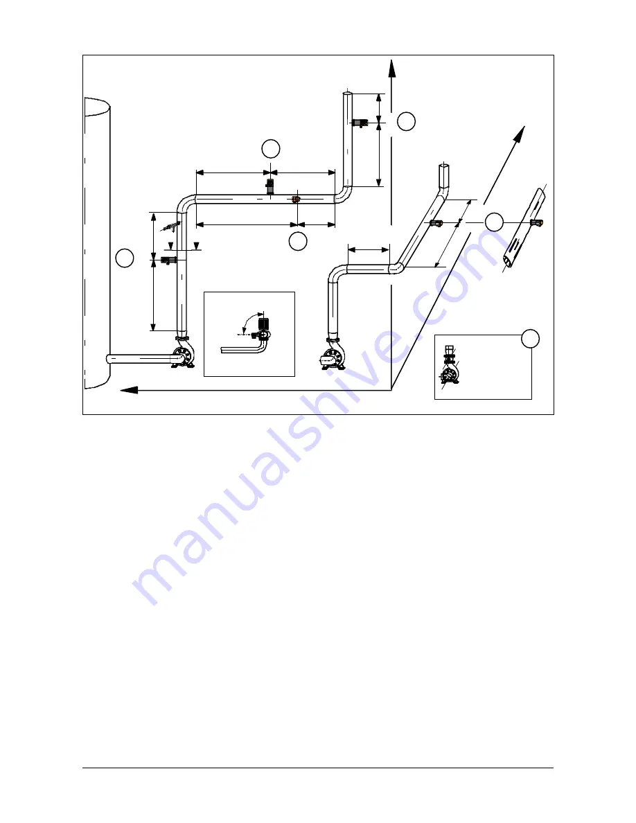
Figure 1.1.2a Preferred mounting locations for SMART-PULP in pipework
1.1.2 Selecting the mounting location
Preferred mounting locations: 1. A, 2. B1, 3. B2
or C (D when pipe turns upward again).
Important considerations:
A. This is the preferred location in terms of the
control loop’s lag time. If the required length of
straight pipe (L1 + L2) is not provided, you can use
an installation tube (Fig. 1.1.2b) that can be welded
in place immediately after conical expansion.
NOTE! The transmitter should be mounted at 90
O
angle to the pump axis (section E-E).
If the vertical section is shorter than the installation
tube or if accessibility is a problem, proceed to
alternative B1.
B1. In this alternative you install the transmitter on
the side of the line to prevent possible air from
disturbing the measurement. Notice that straight
section L1 before the transmitter is 50% longer than
in alternative A. If the straight section is too short,
you can use an installation tube or proceed to
alternative B2 or C.
B2. This method may be considered if the straight
length of horizontal pipe is too short for alternative
B1. Installation on the top side of the pipe always
requires careful consideration, because a substantial
buildup of air in the pipe may affect the
measurement accuracy. We do not recommend this
installation method.
C. You may consider this option when horizontal and
vertical sections before the transmitter are too short.
The double bend before the measurement point will
cause problems when L’ < L1. The whirling flow
produced by the double bend has to be eliminated
with installation tube. In addition, you have to
consider the control loop’s lag time which is
considerably longer in this alternative than in
alternative A.
D. In this method you install the transmitter on the
side of a pipe bend’s outer curve. Distance from pipe
bend is L1. Measurement lag: refer to C.
Other considerations:
F. If a globe valve that will not be continuously fully
open has to be installed between pump and
transmitter, the valve’s axis must be parallel to the
pump’s axis to eliminate whirling flow. The valve
manufacturer’s specifications must be taken into
account.
NOTE! Do not change the pipe diameter between
the pump's conical outlet section and the
transmitter's mounting lo L2 distance.
3
A
B2
B1
C
D
F
Valve and
pump axes
parallel
90
o
Section E-E
SMART-
PULP
axis
E
E
L1
L2
1.5 x L1
L2
L2
L1
L'
L2
L1
L2
L1