3-4
SurgiStat II Service Manual
Alarm Tone
Patient Return Electrode Sensing
The system presents audible and visible alarms when it does not sense a patient
return electrode:
•
When a fault condition occurs, the alarm indicator flashes red, an alarm tone
sounds, and the system disables output power.
•
The red LED alarm indicator remains illuminated until you correct the
condition that caused the alarm condition.
•
Activation attempts during an alarm condition result in an audio alarm and the
alarm indicator flashes.
•
When the alarm condition is resolved, the green single or split-plate indicator
will illuminate.
•
The system measures the return electrode sensing current according to
IEC 60601-1.
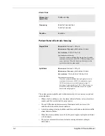
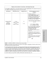
Volume (not
adjustable)
70 dBA ± 5 dBA
Frequency
2 kHz for 1 second, then
1 kHz for 1 second
Duration
4 seconds
Single-Plate
Measurement current: < 100 µA
Measurement frequency: 62.5 kHz ± 2.5 kHz
Set resistance:
0
Ω
to 5
Ω
± 3
Ω
Continuous measurement:
Once the system establishes the single-plate electrode
resistance, an increase of 20
Ω
± 5
Ω
in resistance will
cause an alarm. When the alarm condition exists, the
system deactivates output power.
Split-Plate
Measurement current: < 100 µA
Measurement frequency: 62.5 kHz ± 2.5 kHz
Set resistance:
10
Ω
± 5
Ω
to 135
Ω
± 10
Ω
Continuous measurement:
Once the system establishes the split-plate electrode
resistance, an increase of 40% in resistance or up to
150
Ω
(whichever is less) will cause an alarm. A
decrease of resistance below 4
Ω
± 2
Ω
will cause an
alarm. When the alarm condition exists, the system
deactivates output power.
Summary of Contents for SurgiStat II
Page 1: ...Service Manual SurgiStat II Electrosurgical Generator ...
Page 24: ...2 12 SurgiStat II Service Manual ...
Page 46: ...3 22 SurgiStat II Service Manual Figure 3 20 Bipolar mode waveform ...
Page 60: ...5 6 SurgiStat II Service Manual ...
Page 64: ...6 4 SurgiStat II Service Manual ...
Page 74: ...7 10 SurgiStat II Service Manual ...


