


Con
trols, Indicators,
and
Recept
acles
SurgiStat II Service Manual
2-3
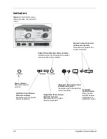
Controls and Indicators Overview
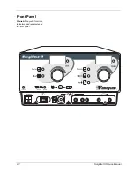
Users may control most SurgiStat II functions from the front panel. Each control
is plainly marked and colored on the front panel for quick reference. Volume
control and a footswitch connector are on the rear panel.
Normal operations involve activating the generator with either a front-connected
handswitch OR a rear-connected footswitch. The following components are the
user interface.
Power Switch
The rocker ON/OFF switch on the lower left corner
allows turning off the generator when the unit is not in
use.
Membrane
Function Switches
The front panel overlay contains six membrane function
switches (sometimes called matrix switches). There is a
membrane switch dedicated for each operational mode.
These switches switch the unit between mode settings.
Power Control
Knobs
These rotary knobs allow you to select the desired RF
power level for all modes of operation. The power
control knobs move in increments of one watt.
Watts Display A &
B (Cut and Coag)
These large power output displays report the
generator’s output power setting from 1 to 120 watts in
one watt increments (at the rated load). During
operation, the numeral output of the display gives the
surgeon an indication of available generator power.
Visual LED
Indictors
Mode LEDs indicate the mode setting.
The YELLOW indicators and controls indicate cutting
and blending operations. A yellow field LED indicates
that either a Pure Cut or Blend mode is activated.
The BLUE indicators and controls indicate desiccation,
fulguration, and bipolar operation. The blue field LED
indicates that either Desiccate, Fulgurate, or Bipolar
mode is activated.
The Footswitch Control LED Indicator indicates which
mode the footswitch is presently in.
Monopolar footswitch control allows the user to activate
the monopolar mode when using footswitch controlled
accessories.
Bipolar footswitch control allows the user to activate the
bipolar mode.
A return electrode indicator displays which type of
patient return electrode is attached to the patient. It also
has an associated audio alarm that sounds when a
patient return electrode is not detected during activation.
Audible Indicators
An activation tone sounds whenever the SurgiStat II
Electrosurgical Generator is activated. The volume may
be adjusted up or down on the rear of the unit.
An alarm sounds during all alarm conditions. You cannot
adjust the volume of this alarm.
Summary of Contents for SurgiStat II
Page 1: ...Service Manual SurgiStat II Electrosurgical Generator ...
Page 24: ...2 12 SurgiStat II Service Manual ...
Page 46: ...3 22 SurgiStat II Service Manual Figure 3 20 Bipolar mode waveform ...
Page 60: ...5 6 SurgiStat II Service Manual ...
Page 64: ...6 4 SurgiStat II Service Manual ...
Page 74: ...7 10 SurgiStat II Service Manual ...