


Thermo DC 200
Control elements
19
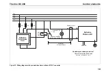
Figure 15: Wiring diagram with pre-selection timer, without DC-DC converter
5A
1
10
11
12
4
5A
5A
2
8
0,
75mm
²
0,
75mm
²
0,
75mm
²
BN
2
1
BK
T. 58
T. 15
T. 30
T. 31
max.
Spheros
Thermo DC
24V
690V DC
at least 30V DC
0.4A
1,5 A
max. 10m
24V DC max. 250mA
Consider prescribed protection!
- Overcurrent protection device
See para.: „Installation“, Fig. 8
External control
input
at least 2.5mm
2
Spheros
Pre-selection
Timer
Operation indicator
Summary of Contents for THERMO DC 200
Page 4: ...IV Thermo DC 200...
Page 34: ...Technical data Thermo DC 200 30 For notes...
Page 35: ...memos...