3
947496
Table:
Provided with the VE8024A are four rubber
pads. Peel pads off their carrier backing and place
at the four corners of the bottom of the unit.
VE8024AR
Rack:
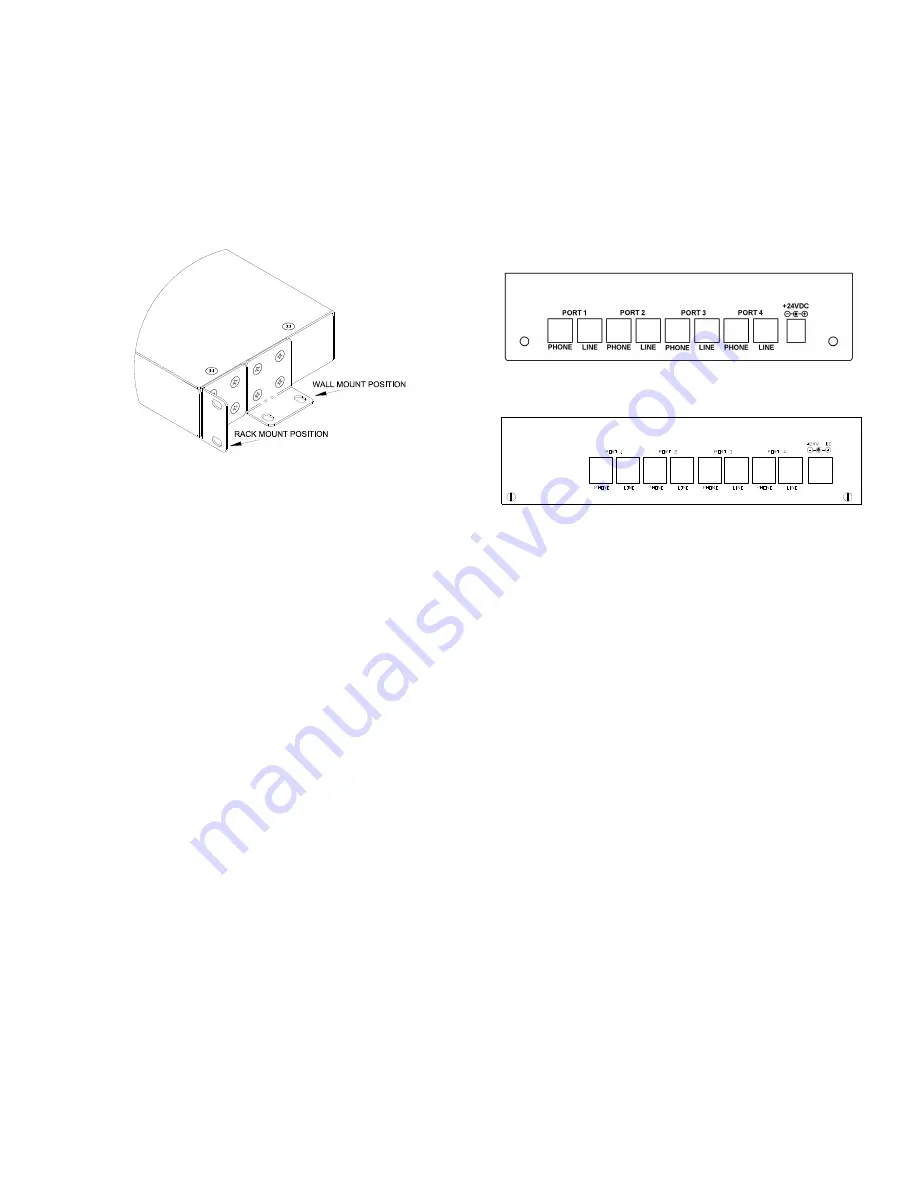
Secure mounting brackets to the
VE8024AR
(See Figure 1). Place the VE8024AR into a
standard 19” rack and secure with proper hardware
(not included).
Figure 1. Mounting
Power Connections
The preferred method of powering a
VE8024A/VE8024AR is via a Power over Ethernet
(PoE) switch meeting the 802.3af specification.
If the rear panel barrel connector is used for power,
the preferred power supply is a Valcom VIP-324D.
Make all required signal connections before
applying power to the unit. If powering via 802.3af,
make sure all signal connections via the back
panel are made then connect the
VE8024A/VE8024AR to the Ethernet switch.
If power is supplied via the barrel connector, make
sure all signal connections are secure. Attach the
unit to the network via the front panel RJ45
Ethernet connector. Apply power by plugging the
power supply into the VE8024A/VE8024AR via the
barrel connector on the rear of the
VE8024A/VE8024AR.
Network Connection
The VE8024A/VE8024AR has one RJ45 Ethernet
network connector on the front panel.
Use the supplied patch cable to connect the
VE8024A/VE8024AR to an Ethernet switch
Signal Connections
FXS Connection:
Connect standard analog FXS
circuits, capable of providing calling party
disconnect, to the VE8024A/VE8024AR via the
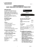
rear panel RJ11 jacks labeled Port 1 Line, Port 2
Line, Port 3 Line and Port 4 Line. Tip and Ring
appear on pins 3 and 4 of these jacks.
Failover Telephone Connections
:
Connect standard analog telephones to the
VE8024A/VE8024AR via the rear panel RJ-11
jacks labeled Port 1 Phone, Port 2 Phone, Port 3
Phone and Port 4 Phone. Tip and Ring appear on
pins 3 and 4 of these jacks.
Rear View: VE8022A
Rear View: VE8024AR
Setup
Information specific to your application will need to
be programmed into the VE8024A/VE8024AR
using a computer. The PC used for programming
should be connected to the same subnet as the
VE8024A/VE8024AR. Setup will be done using
the IP Solutions Setup Tool. Download the latest
version of the free IP Solution Setup Tool from
Valcom website at www.valcom.com/vipsetuptool.
Status Indicator Lights
The VE8024A/VE8024AR has 3 status indication
lights on the front panel:
STATUS:
Flashes during normal operation and
solid during system startup.
LINK:
Indicates 100 Mbit Ethernet connection
when illuminated. No activity indicates 10 Mbit
connection.
ACT:
Indicator flashes to indicate network activity.


