background image

User's Guide ______________________________________________________________________  

8 ___________________________________________________________________ M210297EN-E 


This page intentionally left blank. 


Summary of Contents for HUMICAP HM70

Page 1: ...USER S GUIDE Vaisala HUMICAP Hand Held Humidity and Temperature Meter HM70 M210297EN E...

Page 2: ...echanical including photocopying nor may its contents be communicated to a third party without prior written permission of the copyright holder The contents are subject to change without prior notice...

Page 3: ...TION 9 Vaisala HUMICAP Hand Held Temperature and Humidity Meter HM70 9 Display Parameters 9 CHAPTER 3 PREPARATIONS BEFORE USE 13 Installing and Recharging the Batteries 13 Turning ON the Device 14 CHA...

Page 4: ...hemical Purge Optional 34 Turning Chemical Purge ON 34 Sensor Preheat Optional 36 Turning Sensor Preheat ON OFF 37 CHAPTER 9 CALIBRATION AND ADJUSTMENT OF TRANSMITTERS 39 HM70 in Checking and Adjustin...

Page 5: ...W19 Transmitter 56 CHAPTER 10 MEASURING OTHER PARAMETERS SIMULTANEOUSLY 57 CHAPTER 11 ANALOG OUTPUT CONNECTION 59 Selecting and Scaling the Analog Output 59 CHAPTER 12 CALIBRATION AND ADJUSTMENT OF HM...

Page 6: ...cies of Calculated Variables 73 Accuracy of Dewpoint Temperature C 73 Accuracy of Mixing Ratio g kg 73 Accuracy of Wet Bulb Temperature C 74 Accuracy of Absolute Humidity g m 74 General 74 MI70 Indica...

Page 7: ...ns Manual Code Description M210297EN A May 2002 First release M210297EN B April 2004 M210297EN C January 2005 M210297EN D April 2006 M210297EN E May 2007 Sensor types updated to HUMICAP 180R and HUMIC...

Page 8: ...warns you of a potential hazard If you do not read and follow instructions carefully at this point the product could be damaged or important data could be lost NOTE Note highlights important informati...

Page 9: ...art shall should Vaisala so require be sent to the works of Vaisala or to such other place as Vaisala may indicate in writing freight and insurance prepaid and properly packed and labelled unless Vais...

Page 10: ...User s Guide ______________________________________________________________________ 8 ___________________________________________________________________ M210297EN E This page intentionally left blank...

Page 11: ...y to use Microsoft Windows software which allows an easy way to handle measurement data using a serial line or a USB instrument cable Vaisala HM70 is delivered with a factory calibration certificate D...

Page 12: ...____ 10 __________________________________________________________________ M210297EN E 2 Td shows dewpoint over water throughout the entire measurement range Figure 1 MI70 indicator 1 Recharger connec...

Page 13: ...E Basic probe for relative humidity and temperature measurement Preheat and chemical purge options available HMP75B HMP76 PROBE Rugged probe with a long stainless steel shaft Preheat and chemical purg...

Page 14: ...User s Guide ______________________________________________________________________ 12 __________________________________________________________________ M210297EN E This page intentionally left blank...

Page 15: ...s shipped from the factory 2 Recharge the battery pack as follows Plug in the recharger connector to the base of the indicator and connect the recharger to a wall socket A battery symbol in the corner...

Page 16: ...ge later as well see page 24 4 To change the date select Date and press SET Change the date by using any of the buttons To confirm the date press OK The default date presentation format is year month...

Page 17: ...probe HM70 series probe versions B remember to carry out chemical purge regularly see page 34 4 In case there is a risk for condensation use the optional preheat HM70 series probe versions B when inst...

Page 18: ...0 C and the relative humidity 100 RH a difference of 1 C between the environment and the probe causes an error of 6 RH When the humidity is 90 RH the corresponding error is 5 4 RH A temperature differ...

Page 19: ...S Buttons and Navigation Figure 4 MI70 buttons Press down the POWER ON OFF button until the indicator turns on off Press the SHORTCUT buttons to activate the function shown above the button Press any...

Page 20: ...3 x mixing ratio g kg gr lb Tw wetbulb temperature C F H2O humid air volume dry air volume ppm pw water vapour pressure hPa lb in2 pws saturation water vapour pressure hPa lb in2 h enthalpy kJ kg Btu...

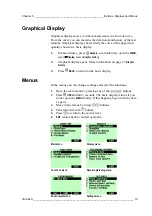
Page 21: ...tively open the MENU select Display select Graphic history 2 Graphical display opens More information on page 23 Graphic history 3 Press BACK to return to the basic display Menus In the menus you can...

Page 22: ...User s Guide ______________________________________________________________________ 20 __________________________________________________________________ M210297EN E This page intentionally left blank...

Page 23: ...Gauge pressure given in the unit of bar Indicates the pressure difference between normal atmospheric pressure and the actual process pressure bara Absolute process pressure given in the unit of bar p...

Page 24: ...To change the unit move on the quantity you want by using the arrow buttons then press UNIT 6 To hide a quantity move on the quantity you want to hide by using the arrow buttons then press HIDE 7 Pre...

Page 25: ...is of the saving date and time All the individual readings data points are stored in a same file marked with The file remains in the indicator memory even if the indicator is switched OFF 7 To view th...

Page 26: ...ress the buttons 7 Press BACK and EXIT to return to the basic display User Interface Selecting Language You can select any of the following languages as an user interface language English German Frenc...

Page 27: ...the choice you want press SELECT 6 Press EXIT to return to the basic display Changing Shortcut Keys As a default the three shortcut keys refer to the functions Graphic Hold Save and Record If needed...

Page 28: ...me To have correct date and time in recorded data files set the date and time according to the following instructions 1 Open the MENU press OPEN 2 Select Setting press 3 Select Date and time press 4 T...

Page 29: ...information on the probe Press OK and EXIT to return to the basic display Reverting to Factory Settings You can revert to factory settings to clear all changed settings and recorded data on the indic...

Page 30: ...User s Guide ______________________________________________________________________ 28 __________________________________________________________________ M210297EN E This page intentionally left blank...

Page 31: ...data press 3 To change interval select Interval press SET 4 Select the measurement interval with arrow buttons Measurement intervals and the maximum recording times are shown in the table below Maxim...

Page 32: ...off during recording to save battery Display message tells you that recording continues undisturbed even when power is off If the indicator is switched off during recording the progress bar is shown o...

Page 33: ...check how much there is free space in the memory 1 Open the MENU press OPEN 2 Select Recording Viewing press 3 Select Memory status press SHOW to see the amount of memory in use and the estimated fre...

Page 34: ...ection cable it is easy to transfer logged and real time measurement data from the HM70 to a PC When using the USB cable consider the following the MI70 Link program contains the driver needed for the...

Page 35: ...Alarm press 4 Select Quantity and press SET to choose a quantity 5 Select quantity press SELECT Only one quantity can be chosen at a time Only active quantities can be selected To change the active qu...

Page 36: ...see page 25 Chemical Purge Optional Chemical purge is an optional feature of the HM70 series humidity probes B version probes In some specific applications the sensor gain may decrease gradually due t...

Page 37: ...ge takes up to 6 minutes During that time there are no readings on a display A message display appears once in 15 seconds and it tells you the time required to complete the chemical purge The chemical...

Page 38: ...up to 4 minutes This is to prevent possible condensate from the sensor When setting the probe from outdoor conditions into warm and humid conditions there can be large temperature difference between t...

Page 39: ...t the probe to the process 5 When sensor preheat is done a display message tells that operation is completed and the basic display with readings returns Sensor preheat is taking about 4 minutes at max...

Page 40: ...User s Guide ______________________________________________________________________ 38 __________________________________________________________________ M210297EN E This page intentionally left blank...

Page 41: ...fixed transmitter s reading against a calibrated reference probe on the HM70 One or two point calibrations can be done to industrial transmitters and modules HMP230 240 series HMT320 330 series HMM21...

Page 42: ...be checked 1 Connect the end of the HMA6070 connection cable for HM60 70 series or HMA2030 connection cable for HM20 30 series cable to either of the HM70 s connector port located on the bottom of th...

Page 43: ...holder for the HMP76 probe to attach the probe next to the probe of HMD60 70 or HMD20 30 order code for the probe holder HM36915 7 Wait until the readings have stabilized can take up to 20 minutes If...

Page 44: ...HMT100 motherboard 2 Connect the other end of the connection cable to either of the HM70 s connector ports located on the bottom of the indicator 3 Turn on both devices or just the HM70 if HMT100 is...

Page 45: ...nly one reference condition please take care that the reference condition represents the measuring environment MI70 indicator is used now only as a terminal for visualizing and setting the transmitter...

Page 46: ...t reference condition may take 30 minutes or more You can follow the stabilization from the GRAPH display 12 Enter the correct reference value in the first condition with the arrow buttons Press OK 13...

Page 47: ...t chamber and insert the probe into the NaCl salt chamber 13 Press READY when the reading has stabilized in the NaCl salt chamber may take 30 minutes or more You can follow the stabilization from the...

Page 48: ...n connector of the HMM210 module 3 Connect the other end of the calibration cable to either of the HM70 s connector port located on the bottom of the indicator see Figure 7 on page 40 4 Turn on the HM...

Page 49: ...ps from 1 to 12 and continue as follows 13 Ensure that the probes are located in the same conditions 14 Wait until the readings have stabilized If the difference between the humidity readings is less...

Page 50: ...two reference humidities shall be at least 50 MI70 indicator is working as a communicator in the calibration procedure Follow the steps from 1 to 12 and continue as follows 13 Insert the transmitter...

Page 51: ...211339 calibration cable to the RS232 connector in the mother board of the HMP300 series transmitter 2 Connect the other end of the calibration cable to either of the HM70 s connector port located on...

Page 52: ...IT to return to the basic display 14 Replace the CAL DIS jumper 15 Switch off the MI70 and detach the calibration cable from MI70 and from the transmitter 1 Point Adjustment by Using a Calibrator When...

Page 53: ...se the adapter fitting 13 5 mm on the measurement hole if you calibrate probes of HMT324 HMT325 HMT327 and HMT328 Follow the steps from 1 to 8 and continue as follows 9 Remove the filter from the tran...

Page 54: ...alibration method 1 Connect the 211339 calibration cable to the SERVICE PORT connector on the mother board of the HMP330 2 Connect the other end of the calibration cable to either of the HM70 s connec...

Page 55: ...s or more If you are near the probes do not breathe in their direction 10 Press ADJUST to continue adjusting 11 Press To same asRHIi I press SELECT MI70 recognizes always the port to which the HMP70 s...

Page 56: ...Calibrator Note that the difference between the two reference humidities shall be at least 50 MI70 indicator is used now in communication If you use humidity calibrator HMK15 please use the adapter f...

Page 57: ...on the measurement hole if you calibrate probes of HMT334 HMT335 HMT337 and HMT338 Follow the steps from 1 to 8 on page 52 and continue as follows 9 Remove the filter from the transmitter s probe and...

Page 58: ...ector position Vaisala logo on top of the DMW19 4 Connect the other end of the calibration cable to either of the HM70 s connector port located on the bottom of the indicator see Figure 7 on page 40 5...

Page 59: ...obes Two different probes can be used simultaneously 1 Turn off the device 2 Connect the DMP70 GMP70 probe to the other connector port in the bottom of the indicator 3 Turn on the device 4 Check that...

Page 60: ...User s Guide ______________________________________________________________________ 58 __________________________________________________________________ M210297EN E This page intentionally left blank...

Page 61: ...tput To get analog measurement data you need the analog output signal cable see list of accessories on page 77 One voltage signal channel 0 1 0V can be scaled for the selected quantity 1 Connect the a...

Page 62: ...al press SET If the analog output is ON take it OFF Set the low value by using arrow buttons Press button to choose the sign of the value Press OK to make the setting 8 Select 1 0V to set the value fo...

Page 63: ...e contact information on page 68 Alternatively user can calibrate and adjust HM70 by following the instructions given in this chapter When using Vaisala humidity calibrator HMK15 use the adapter fitti...

Page 64: ...ture adjustment first 2 Check that the HM70 is switched on 3 If chemical purge option is available perform it before adjustment see page 34 4 Take out the screw from the probe handle to expose the cal...

Page 65: ...ne 15 Adjustment has been carried out Press BACK to exit the adjustment mode press EXIT to return to the basic display 16 Replace the screw onto calibration button You can attach a sticker on the cali...

Page 66: ...on press ADJUST to select the adjustment method 1 point adjustment or 2 point adjustment 1 Point Adjustment Follow the steps from 1 to 4 and continue as follows 5 Select 1 point adjustment press SELEC...

Page 67: ...w buttons Press OK 8 Set the probe to the higher reference temperature You can follow the stabilization from the GRAPH display Press READY when the reading is stabilized 9 Give the higher reference te...

Page 68: ...User s Guide ______________________________________________________________________ 66 __________________________________________________________________ M210297EN E This page intentionally left blank...

Page 69: ...page 68 1 Open the back plate of the indicator by opening the screw of the back plate 2 Remove the old battery pack Detach the black connector by pulling up carefully from the wires 3 Connect the bla...

Page 70: ...ment In case of constant error please contact Vaisala Service Centers see page 68 Error Messages Voltage required for Purge unavailable Voltage required for Preheat unavailable Eeprom read write error...

Page 71: ...tact information and instructions are available from www vaisala com Addresses of the Service Centers are provided in section Vaisala Service Centers on page 70 Please have the following information o...

Page 72: ...____ M210297EN E Vaisala Service Centers Vaisala Service Centers perform calibrations and adjustments as well as repair and spare part services See contact information below Vaisala Service Centers al...

Page 73: ...Humidity Measurement range 0 100 RH Accuracy including non linearity hysteresis and repeatability at 15 25 C 1 RH 0 90 RH 1 7 RH 90 100 RH at 20 40 C 1 0 0 008 x reading RH at 40 20 C 40 180 C 1 5 0 0...

Page 74: ...with sintered filter Temperature Measurement ranges HMP75 20 60 C HMP76 50 120 C to 180 C temporarily HMP77 70 180 C Accuracy at 20 C 0 2 C Figure 10 Accuracy over temperature range Temperature sensor...

Page 75: ...3 40 3 24 1 76 1 27 1 03 0 88 0 78 0 71 0 65 0 61 0 58 60 3 60 1 96 1 42 1 14 0 97 0 86 0 78 0 72 0 67 0 64 80 4 01 2 18 1 58 1 27 1 08 0 95 0 86 0 79 0 74 0 70 100 4 42 2 41 1 74 1 40 1 19 1 05 0 95...

Page 76: ...55 1 37 1 24 1 13 1 05 0 99 Accuracy of Absolute Humidity g m Relative humidity Temp 10 20 30 40 50 60 70 80 90 100 40 0 004 0 004 0 005 0 005 0 005 0 006 0 006 0 006 20 0 023 0 025 0 027 0 029 0 031...

Page 77: ...neral Operating temperature range 10 40 C Operating humidity 0 100 RH non condensing Menu languages English Finnish French German Spanish Swedish Chinese Russian Japanese Display LCD with backlight Gr...

Page 78: ...eration times in continuous use 48 h typical at 20 C data logging use at least 30 days Power consumption during charge 10W max Charging time 4 hours General about Vaisala Hand Held Humidity and Temper...

Page 79: ...320 330 series 211339 Connection cables for DMW19 211917ZZ Carrying cases Carrying case for one probe HMP75 or HMP77 MI70CASE Carrying case for two probes HMP75 and HMP76 or GMP probe MI70CASE2 Probe...

Page 80: ...___________________________________________________________ 78 __________________________________________________________________ M210297EN E Dimensions in mm inches 2 0 5 8 0 7 1 1 8 4 6 5 12 0 47 MI...

Page 81: ...________________ Technical Specifications VAISALA _______________________________________________________________________ 79 HMP76 Probe HMP77 Probe 12 0 47 37 5 1 48 79 5 3 13 99 5 3 92 M9 1 HMP77 Pr...

Page 82: ...User s Guide ______________________________________________________________________ 80 __________________________________________________________________ M210297EN E This page intentionally left blank...

Page 83: ...www vaisala com M210297EN...

Reviews: