background image

0020253094_05 ecoTEC sustain Installation and maintenance instructions

39

7.

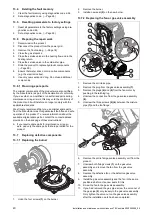
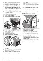
Check that the sealing ring in the air intake pipe is posi-
tioned correctly in the seal seat.

8.

Reconnect the air intake pipe to the intake stub.

9.

Secure the air intake pipe with the retaining screw.

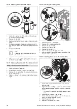
10. Check the gas flow pressure.

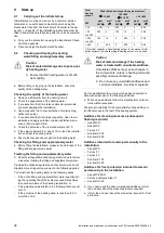
12.14 Draining the product

1.

Close the service valves of the product.

2.

Start check programme P.06 (prioritising diverter valve
mid-position).

3.

Open the draining cock.

4.

Make sure that the cap of the automatic air vent on
the internal pump is open so that the product can be
drained fully.

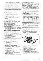
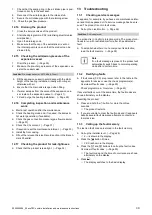
12.15 Checking the admission pressure of the

expansion vessel

1.

Drain the product. (

Page 39)

2.

Measure the pre-charge pressure of the expansion ves-
sel at the vessel valve.

Condition

: Pre-charge pressure < 0.075 MPa (0.75 bar)

Fill the expansion vessel in accordance with the static
height of the heating installation; ideally with nitrogen,
otherwise with air.

Ensure that the drain valve is open when filling.

3.

If water escapes from the valve of the expansion ves-
sel, replace the expansion vessel (

Page 41).

4.

Fill and purge the heating installation. (

Page 29)

12.16 Completing inspection and maintenance

work

Start a test operation after the maintenance.

Check the heating mode and, if required, the domestic
hot water generation (if available).

Check the gas connection pressure (gas flow pressure).
(

Page 30)

Check the CO

content. (

Page 31)

If required, reset the maintenance interval. (

Page 33)

Install the front casing.

Fill out the relevant Service Record section in the Bench-
mark Checklist.

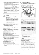
12.17 Checking the product for leak-tightness

Check that the product is leak-tight. (

Page 32)

13 Troubleshooting

13.1

Checking service messages

appears, for example, if you have set a maintenance inter-

val and this has passed or if a service message has been is-
sued. The product is not in fault mode.

Call up the Live Monitor. (

Page 26)

Condition

: S.46 is displayed.

The product is in Comfort protection mode. The product con-
tinues to run with restricted comfort after it has detected a
fault.

To establish whether or not a component is defective,
read the fault memory. (

Page 39)

Note

If no fault message is present, the product will
automatically switch back to normal operating
mode after a certain time.

13.2

Rectifying faults

If fault codes (F.XX) are present, refer to the table in the
appendix for advice or use the check programme(s).
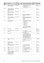
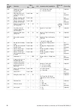
Overview of fault codes (

Page 50)

Check programmes

Overview (

Page 45)

If several faults occur at the same time, the fault codes are
shown alternately on the display.

Resetting the product:

Press and hold the

button for more than three

seconds.

The product restarts.

If you are unable to clear the fault code and it reappears
despite several fault clearance attempts, contact cus-
tomer service.

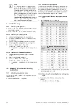
13.3

Calling up the fault memory

The last ten fault codes are stored in the fault memory.

Call up the installer level. (

Page 26)

d.-- is shown in the display.

Press the

button 2 times.

F.XX is shown in the display.

Press the

and

buttons to call up the fault codes.

Overview of fault codes (

Page 50)

The fault code and the time of occurrence are shown
alternately on the display.

Press

.

The display switches to the basic display.

Summary of Contents for ecoTEC sustain 24

Page 1: ...en Installation and maintenance instructions ecoTEC sustain 24 28 34 0020253094_05 04 11 2020...

Page 2: ...plementary water 28 9 3 Filling the condensate siphon 29 9 4 Switching the product on and off 29 9 5 Preventing low water pressure 29 9 6 Flushing the heating installation for the first time cold 29 9...

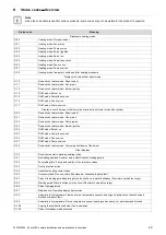
Page 3: ...ppendix 44 A Inspection and maintenance work 44 B Check programmes Overview 45 C Overview of diagnostics codes 45 D Status codes Overview 49 E Overview of fault codes 50 F Wiring diagrams 52 F 1 Wirin...

Page 4: ...y direct use in industrial or commercial processes Any use other than those described in these instructions and any use that goes beyond what is described here 1 2 Qualification The person carrying ou...

Page 5: ...ercially available soft soap to aid installa tion 1 3 3 Electricity The power supply terminals L and N remain live even if the unit main switch is switched off To prevent electric shocks proceed as fo...

Page 6: ...at floor level If the product is installed below ground level liquid gas may accumulate at floor level if there are any leaks In this case there is a risk of explosion Make sure that liquid gas cannot...

Page 7: ...aillant group com Spares Enquiries Telephone 01773 596 615 To register your Vaillant appliance visit https self service vaillant co uk warranty registration Vaillant is a licensed member of the Benchm...

Page 8: ...g s 13 6 g s 16 5 g s Released system types C13 C33 C43 C53 C13 C33 C43 C53 C13 C33 C43 C53 Min flue gas temperature 44 41 43 Max flue gas temperature 85 95 99 Nominal efficiency at 80 60 C 98 9 98 9...

Page 9: ...er flow T 20 K 797 l h 797 l h 797 l h P heating at nominal flow T 20 K bypass closed 0 024 MPa 0 024 MPa 0 026 MPa P heating at nominal flow T 20 K bypass in the position set at the factory 0 043 MPa...

Page 10: ...ecoTEC sustain 0020253094_05 VUW 246 7 2 H GB VUW 286 7 2 H GB VUW 346 7 2 H GB Standby electrical power consump tion 1 6 W 1 8 W 2 6 W Level of protection IPX4D IPX4D IPX4D Permissible connected vol...

Page 11: ...wer millions of people to lead affordable low energy life styles For more information visit energysavingtrust org uk 5 3 Information on the identification plate The identification plate is mounted on...

Page 12: ...lation Servicing company or Vaillant service 5 6 2 Overheating Safety The boiler software is designed to recognise the potential for an overheat lockout and will shutdown before this happens To restar...

Page 13: ...nnections 1 Enclosed documentation 6 2 Dimensions 99 164 75 110 135 338 58 58 123 123 440 125 180 40 123 123 183 65 65 600 720 A 10 1 8 9 10 11 12 2 4 5 6 7 2 4 3 5 6 7 1 Condensate siphon condensate...

Page 14: ...suitable for supporting the load 3 The minimum clearances from the boiler case are main tained 6 5 Compartment Ventilation The boilers are very high efficiency appliances As a consequence the heat los...

Page 15: ...lding material Vertical flue clearance to combustible building material 500 mm 1 500 mm J Above below and either side of an opening door air vent or opening window 300 mm K Diagonally to an opening do...

Page 16: ...nce from pluming depending on site conditions Terminals must be positioned so to avoid combustion products entering the building Support the flue at approximately one metre intervals and at a change o...

Page 17: ...st be positioned to provide minimum of 50 mm clearance from any part of the terminal and be central over the terminal The guard should be similar to that shown in the figure 6 6 3 3 Vertical Concentri...

Page 18: ...nstalling the side section 6 10 1 Removing the side section 2X A B C D Caution Risk of material damage caused by mech anical deformation Removing both side sections may cause mechanical distortion in...

Page 19: ...the gas group indicated on the data plate 7 3 Purging the liquid gas tank If the liquid gas tank is not purged properly this may result in ignition problems Ensure that the liquid gas tank has been p...

Page 20: ...freeze and build into a larger ice plug As with other pipe work insulate the condensate dis charge pipe to minimise any risk of freezing and beware when crossing cavities that the fall is maintained...

Page 21: ...t terminate in rain water drain 7 8 1 6 Internal termination downstream of sink waste 100mm 32mm 22mm 3 m Open end of pipe direct into gulley below ground level but above water level Susceptible to si...

Page 22: ...cal data 2 Remove the connection piece for the air flue pipe this is installed at the factory Page 22 3 If required install the connection piece for the air flue pipe 80 125 mm diameter Page 22 7 10 2...

Page 23: ...onduct ors is not damaged 7 Only strip inner conductors just enough to establish stable connections 8 To avoid short circuits resulting from loose individual wires fit conductor end sleeves on the str...

Page 24: ...s not covered or blocked 14 Close the electronics box 7 11 5 Connecting controls to the electronics 24V RT BUS Burner off X106 BUS 24 V BUS RT B off Burner off RT 24V BUS X2 X41 X22 24V RT BUS Burner...

Page 25: ...6 Connecting additional components via VR 40 2 in 7 multi functional module 1 Install the components in accordance with the respect ive instructions Condition Components connected to relay 1 Activate...

Page 26: ...parameters marked as adjustable in the table of diagnostics codes to adapt the product to the install ation and customer requirements 8 4 1 Setting a diagnostics code 1 Call up the installer level Pag...

Page 27: ...eck programme The display shows the check programme 7 Press to exit the check programme OFF is shown in the display The display changes to show the check pro grammes 8 Press the button 2 times to exit...

Page 28: ...ions and technical rules do not stipulate more stringent requirements the following applies You must treat the heating water in the following cases If the entire filling and supplementary water quanti...

Page 29: ...ther all thermostatic radiator valves and both service valves on the product are open 2 Connect a hose to the drain valve that is located at the lowest position in the heating system 3 Open the radiat...

Page 30: ...recirculation using the air analysis point 3 Use a flue gas analyser 4 If you discover unusual levels of CO or CO 2 in the sup ply air search for the leak in the flue system or for signs of flue gas...

Page 31: ...tighten the sealing screw 2 for the measuring nipple Open the gas stopcock 1 Check the test nipple for gas tightness Reset boiler controls for normal operation Record the appliance gas inlet working p...

Page 32: ...llation 10 1 Activating diagnostics codes You can find the setting options in the diagnostics codes in the installer level Set a diagnostics code Page 26 10 2 Burner anti cycling time To prevent frequ...

Page 33: ...On completion of the set operating hours you must set the maintenance interval again 10 5 Setting the pump output Validity VUW 246 7 2 H GB OR VUW 286 7 2 H GB OR VUW 346 7 2 H GB The product is equi...

Page 34: ...missioning checklist located at the rear of this document For IE Complete a Declaration of Conformity to indicate compliance to I S 813 An example of this is given in the current edition of I S 813 Wh...

Page 35: ...e The gas flow rates Correctness of electrical water and gas connections Correctness of the water pressure The condition of the whole system in particular the con dition of radiator valves evidence of...

Page 36: ...leum gas P Liquefied pet roleum gas P CO at full load 10 1 0 2 vol 10 3 0 2 vol Set for Wobbe index W 21 34 kW h m 21 34 kW h m O at full load 5 1 0 8 vol CO at full load 250 ppm 250 ppm CO CO 0 0025...

Page 37: ...ou notice any signs of damage replace the relevant insulating mat 12 8 Cleaning the heat exchanger 1 Protect the open electronics box from spraying water 1 3 4 2 2 Do not undo the four nuts on the thr...

Page 38: ...ter side 3 Remove the connector from the connection for the pro duct s cold water pipe 4 Clean the strainer in the cold water inlet without remov ing it 12 12 Cleaning the heating filter 1 2 3 2 5 4 1...

Page 39: ...out the relevant Service Record section in the Bench mark Checklist 12 17 Checking the product for leak tightness Check that the product is leak tight Page 32 13 Troubleshooting 13 1 Checking service...

Page 40: ...manufacturer as this guarantees fault free and safe operation of the product To receive information about the available original spare parts contact the contact address provided on the back page of th...

Page 41: ...section of the retainer 8 Move the bracket round to the opposite side and attach the upper screw 1 to the side 9 Pull the heat exchanger downwards and to the right and remove it from the product 10 I...

Page 42: ...Page 23 3 Pull the plug out of the PCB 4 Undo the clips on the PCB 5 Remove the PCB 6 Install the new PCB in such a way that it clicks into the groove at the bottom and into the clip at the top 7 Plug...

Page 43: ...75mm 13 8 Completing repair work 1 Establish the power supply 2 Switch the product back on if this has not yet been done Page 29 3 Install the front casing 4 Open all service valves and the gas stopc...

Page 44: ...structions Annually 12 If the gas flow rate lies outside of the tolerances specified in these in structions eliminate the fault in accordance with the regulations and the current technology Annually 1...

Page 45: ...the automatic purging function is activated The function is activated in the small hot water circuit for four minutes and then in the heating circuit for six minutes This function cannot be manually s...

Page 46: ...ixed rotational speeds Section Setting the pump output 0 Adjustable d 15 Pump speed Current value Not adjustable d 16 Status of the 24 V room thermostat Current value off Heating off on Heating activa...

Page 47: ...r filling 100 Domestic hot water Not adjustable d 36 Value for the domestic hot water flow rate Current value l min Applies to Combi boiler Not adjustable d 39 Water temperature in the solar circuit C...

Page 48: ...Running time in heating mode Current value h Running time Display value x 100 Not adjustable d 81 Running time in domestic hot water mode Current value h Running time Display value x 100 Not adjustabl...

Page 49: ...de Fan prerun S 22 Domestic hot water mode Pump prerun S 23 Domestic hot water mode Burner ignition S 24 DHW mode Burner on S 25 DHW mode Pump fan overrun S 26 DHW mode Fan overrun S 27 DHW mode Pump...

Page 50: ...ssure switch has triggered air in gas gas flow pressure too low thermal cut out has triggered incorrect gas injector incorrect spare gas valve assembly fault on the gas valve assembly mul tiple plug o...

Page 51: ...r in the product flow or return temperature sensor incorrectly attached to the pipe F 84 Fault Flow return temperature sensor Values not consistent difference between flow and return 6 K Flow and retu...

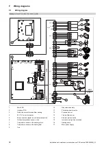
Page 52: ...ff X106 X41 1 3 4 1 3 3 1 2 M 1 3 4 6 1 2 3 M 5 4 2 1 2 1 2 1 N L 24V 230V 24V 230V 2 11 12 13 15 1 7 8 3 4 5 9 10 14 17 16 6 1 Main PCB 2 Interface PCB 3 Safety thermostat for underfloor heating 4 24...

Page 53: ...1 2 M 1 3 4 6 1 2 3 M 4 3 2 1 2 1 2 1 N L L 24V 230V 24V 230V 5 4 2 1 5 6 7 8 X12 L N X51 X51 X51 11 12 13 15 1 7 8 9 10 14 17 16 3 4 5 6 2 1 Main PCB 2 Interface PCB 3 Safety thermostat for underflo...

Page 54: ...mer and they should be made aware it is ultimately their responsibility to register with the manufacturer within the allotted time period It is essential that the boiler is serviced in line with the m...

Page 55: ...t left at factory settings Yes No If no what is the maximum central heating output selected kW Dynamic gas inlet pressure mbar C Central heating return temperature C System correctly balanced rebalanc...

Page 56: ...LER delete as appropriate Date Engineer name Company name Telephone No Gas Safe registration No Max rate CO ppm CO CO CO Min rate CO ppm CO CO CO undertaken in accordance with manufacturers instructio...

Page 57: ...LER delete as appropriate Date Engineer name Company name Telephone No Gas Safe registration No Max rate CO ppm CO CO CO Min rate CO ppm CO CO CO undertaken in accordance with manufacturers instructio...

Page 58: ...specify how to set boiler to minimum rate contact Technical Helpline for advice CHECK CO AND COMBUSTION RATIO AT MINIMUM RATE With boiler still set at minimum rate insert analyser probe into flue gas...

Page 59: ...as Council Number 11 Gas family check performing 19 Gas group 19 Gas setting 30 Gas type 19 Gas valve assembly replacing 40 Guarantee and Customer Service 7 H Handing over to the end user 34 Heat exch...

Page 60: ...60 Installation and maintenance instructions ecoTEC sustain 0020253094_05 Unit connection piece removing 22 V Validity of the instructions 11 Volume flow sensor 42 W Weight 17...

Page 61: ......

Page 62: ......

Page 63: ......

Page 64: ...lisher manufacturer Vaillant GmbH Berghauser Str 40 D 42859 Remscheid Tel 492191 18 0 Fax 492191 18 2810 info vaillant de www vaillant de These instructions or parts thereof are protected by copyright...

Reviews: