


0020253094_05 ecoTEC sustain Installation and maintenance instructions
33
10.3
Setting the maximum heating output
The product's maximum heating output is set to automatic
mode at the factory. If you want to set your own fixed max-
imum heating output, however, you can specify a value un-
der d.00 which equates to the product output in kW.
10.4
Setting the maintenance interval
If you set the maintenance interval, after a configurable num-
ber of burner operating hours, the message that the product
must be serviced appears in the display, together with the
maintenance symbol
.
▶
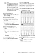
Use diagnostics code d.84 to set the number of operating
hours until the next maintenance is due (number of op-
erating hours = display value x 10). Guideline values can
be found in the following table.
Heat de-
mand
Number
of per-
sons
Guideline value for burner
operating hours until the
next inspection/maintenance
work is due for an average
operating time of one year
(dependent upon the system
type)
5.0 kW
1
‑
2
1050 h
2
‑
3
1150 h
10.0 kW
1
‑
2
1500 h
2
‑
3
1600 h
15.0 kW
2
‑
3
1800 h
3
‑
4
1900 h
20.0 kW
3
‑
4
2600 h
4
‑
5
2700 h
25.0 kW
3
‑
4
2800 h
4
‑
6
2900 h
> 27.0 kW
3
‑
4
3000 h
4
‑
6
3000 h
The values stated correspond to an average operating time
of one year.
If you do not set a numerical value but do set the symbol
"
– – –
", the function is not active.
Note
On completion of the set operating hours, you
must set the maintenance interval again.
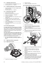
10.5
Setting the pump output
Validity:
VUW 246/7-2 (H-GB)
OR VUW 286/7-2 (H-GB)
OR VUW 346/7-2 (H-GB)
The product is equipped with a speed-regulated high-effi-
ciency pump, which adjusts independently to the hydraulic
conditions of the heating installation.
If you have installed a low loss header in the heating install-
ation, we recommend switching off the speed regulation and
setting the pump output to a fixed value.
▶
If required, change the setting of the pump speed, which
depends on the operating mode, under diagnostics code
d.14.
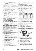
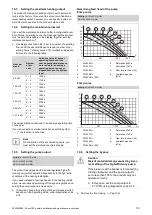
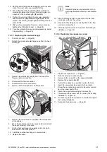
Remaining feed head of the pump
Pump curve
Validity:
VUW 246/7-2 (H-GB)
OR VUW 286/7-2 (H-GB)
6
0
500
1000
1300
A
B
0
5
10
15
20
25
30
35
40
5
3
2
1
4
7
1
PWM 65%
2
PWM 73%
3
PWM 80%
4
PWM 88%
5
PWM 95 to 100%
6
Saturation 25 kPa
7
Saturation 17 kPa
A
Flow rate in circuit (l/h)
B
Available pressure
(kPa)
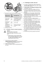
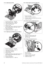
Pump curve
Validity:
VUW 346/7-2 (H-GB)
6
0
500
1000
1400
A
B
0
5
10
15
20
25
30
35
40
5
3
2
1
4
7
1
PWM 65%
2
PWM 73%
3
PWM 80%
4
PWM 88%
5
PWM 95 to 100%
6
Saturation 25 kPa
7
Saturation 17 kPa
A
Flow rate in circuit (l/h)
B
Available pressure
(kPa)
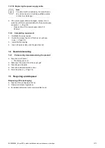
10.6
Setting the bypass
Caution.
Risk of material damage caused by incor-
rect setting of the high-efficiency pump
If the pressure at the bypass is increased (by
turning clockwise) and the pump output is
set to less than 100%, the product may not
operate correctly.
▶
In this case, set the pump output to
5 = 100% using diagnostics code d.14.
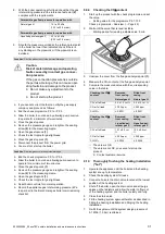
▶
Remove the front casing. (
Summary of Contents for ecoTEC sustain 24
Page 1: ...en Installation and maintenance instructions ecoTEC sustain 24 28 34 0020253094_05 04 11 2020...
Page 61: ......
Page 62: ......
Page 63: ......


