


0020253094_05 ecoTEC sustain Installation and maintenance instructions
19
7
Installation
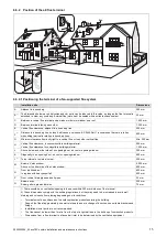
7.1
Preparing for installation
▶
Make sure that the existing gas meter is capable of
passing the rate of gas supply required.
▶
Consider the maximum heat output given in DHW mode.
▶
Install a system separator (to be provided on-site) directly
on the cold water connection for the combi boiler.
▶
Install the following components:
–
Draining cocks at the lowest points in the heating
installation (
→
current version of "BS 2879")
–
A stopcock on the cold water connection
–
A stopcock in the gas pipe
▶
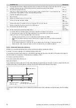
Check that the volumetric capacity of the expansion ves-
sel is sufficient for the system volume.
▽
If the volume of the expansion vessel is insufficient
for the installation.
▶
Install an additional expansion vessel in the heat-
ing return, as close to the product as possible.
▶
Install a non-return flap at the product's outlet
(heating flow).
▶
Install the connection pipes such that they are free from
mechanical stress.
▶
If you use non-diffusion-tight plastic pipes in the heating
installation, ensure that no air gets into the heat gener-
ator circuit.
▶
Only solder connectors if the connectors are not yet
screwed to the service valves.
▶
Only bend connection pipes if they have not yet been
connected to the product.
▶
Flush the heating installation thoroughly before installing
the product.
▶
Check the leak-tightness of the gas valve assembly using
a pressure of
≤
11 kPa (110 mbar).
7.2
Information on the gas group
In the as-supplied condition, the product is preset for opera-
tion with the gas group indicated on the data plate.
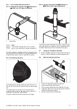
7.3
Purging the liquid gas tank
If the liquid gas tank is not purged properly, this may result in
ignition problems.
▶
Ensure that the liquid gas tank has been purged properly
before installing the product.
▶
If required, contact the filler or the liquid gas supplier.
7.4
Using the correct gas type
Using the incorrect gas type may cause fault shutdowns in
the product. Ignition and combustion noise may occur in the
product.
▶
Only use the gas type listed on the data plate.
7.5
Descaling the water
Scale deposition increases as the water temperature in-
creases.
▶
Descale the water as required.
7.6
Gas family check
Make sure that the product is set up correctly by checking
the gas type. This ensures optimum combustion quality.
▶
Check the gas type as part of routine product mainten-
ance work when replacing components or carrying out
work on the gas route.
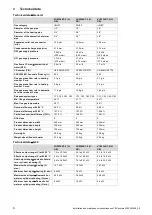
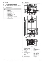
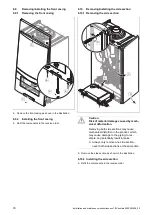
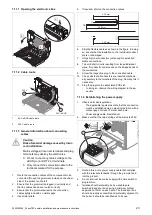
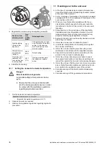
7.7
Gas and water connections
1
2
3
4
5
1
Heating flow connec-
tion, G3/4
2
Hot water connection,
G3/4
3
Gas connection, G1/2
4
Connection for the cold
water supply line, G3/4
5
Heating return connec-
tion, G3/4
1.
Connect the water and gas connections in accordance
with the applicable standards.
2.
Purge the gas pipe before start-up.
3.
Check whether the connections are leak-tight.
4.
Check the entire gas pipe properly for leak-tightness.
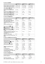
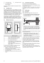
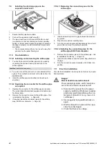
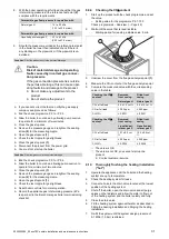
7.8
Connecting the condensate discharge pipe
min.
180
1
2
▶
Follow the instructions listed here and observe directives
and local regulations on condensed water discharge.
▶
Use PVC or another material that is suitable for draining
the non-neutralised condensed water.
▶
If you cannot guarantee that the materials from which the
condensate discharge pipe is made are suitable, install a
system to neutralise the condensate.
Summary of Contents for ecoTEC sustain 24
Page 1: ...en Installation and maintenance instructions ecoTEC sustain 24 28 34 0020253094_05 04 11 2020...
Page 61: ......
Page 62: ......
Page 63: ......


