Vaillant ecoTEC plus VUI Series Installation And Maintenance Instructions Manual Download Page 10

10

Installation and maintenance instructions 0020308121_04

4

Notes on the documentation

Always observe all the operating and installation instruc-
tions included with the system components.

Pass these instructions and all other applicable docu-
ments on to the end user.

These instructions apply for the following products only:

Product article number

VUI 30/40

0010036114

Gas Council Numbers

VUI 30/40CS/1-5 (N-GB) ecoTEC plus 940

47-044-96

These instructions apply only to:

Great Britain

Ireland

5

Product description

5.1

CE marking

The CE marking shows that the products comply with the
basic requirements of the applicable directives as stated on
the declaration of conformity.

The declaration of conformity can be viewed at the manufac-
turer's site.

5.2

UKCA mark

The UKCA marking shows that the products comply with the
basic requirements of the applicable directives as stated on
the declaration of conformity.

The declaration of conformity can be viewed at the manufac-
turer's site.

5.3

Hot Water Association

Vaillant is a full member of the Hot Water Association and
promotes the scheme in association with its cylinder range.
Details are available on the web site www.vaillant.co.uk

5.4

Water Regulations Advisory Scheme

The product meets the requirements of this quality standard.
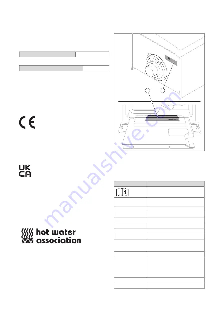
5.5

Data plate

2

1

Two data plates are attached to the product at the factory.
The data plate on the top of the unit

(2)

is always accessible

and contains the basic information for the chimney sweep.
The main data plate

(1)

with all of the information is attached

to the rear of the electronics box. Any information that is not
listed here can be found in separate sections.

Information

Meaning

Read the instructions.

VCI, VUI, VMI, VHR
I

Product with integrated domestic hot
water generation

10 - 36

Nominal heat output

C

Condensing boiler

S

Stainless steel heat exchanger

/1

Product generation

-5

Product equipment

N, E

Gas group

E.g. AT, BE, CH,
DE, DK, ES, FR, IT,
NL, NO, PL, SE

Target market

ecoTEC plus

Marketing name

E.g. I2N, 2N, I2ELw,
I2H, G20

20 mbar

(2.0 kPa)
E.g. I3P, G31

50 mbar (5.0 kPa)

Gas group and gas connection pressure
as set at the factory

Cat.

Gas boiler category

Type

Unit types

Summary of Contents for ecoTEC plus VUI Series

Page 1: ...en Installation and maintenance instructions ecoTEC plus VUI 0020308121_04 31 05 2023...

Page 2: ...stics codes 32 8 4 Running a check programme 32 8 5 Carrying out the actuator test 32 8 6 Calling up the data overview 32 8 7 Calling up status codes 32 8 8 Exiting the menu level 32 8 9 Running the c...

Page 3: ...Temporarily decommissioning 61 14 3 Permanently decommissioning 61 15 Disposing of the packaging 61 Appendix 62 A Tightening torques 62 B Inspection and maintenance work 62 C Installer level 64 D Dia...

Page 4: ...ater cylinders whether in the case of a replacement or for a new installation Using the product for a multiple flue config uration or as a cascade Any direct use in industrial or commercial processes...

Page 5: ...ercially available soft soap to aid installa tion 1 3 3 Air supply Unsuitable or insufficient combustion and room air may lead to material damage but also to life threatening situations Use the data p...

Page 6: ...remove all sealing materials Separate components which may be in ternally damaged by heat from each other Only continue the installation processes once all components have cooled down warm to the tou...

Page 7: ...group com Spares Enquiries Telephone 01773 596 615 To register your Vaillant appliance visit https self service vaillant co uk warranty registration Vaillant is a licensed member of the Benchmark Sch...

Page 8: ...ed gas boiler types C13 C33 C43 C53 NOx class 6 SAP 2009 2012 annual efficiency Weight with packaging incl accessories 66 kg Weight without packaging without water 60 kg Weight when unit is ready for...

Page 9: ...p flow rate 1 8 l min Specific flow rate D T 30 K EN 13203 1 21 0 l min Flow rate T 35 K 18 0 l min Permissible operating pressure 0 95 MPa 9 50 bar Required connection pressure 0 07 MPa 0 70 bar Dome...

Page 10: ...s site 5 3 Hot Water Association Vaillant is a full member of the Hot Water Association and promotes the scheme in association with its cylinder range Details are available on the web site www vailla...

Page 11: ...rol The product the system control and the app show approx imate values for energy consumption energy yields and ef ficiencies which are extrapolated based on calculation al gorithms The values that a...

Page 12: ...pens To restart the boiler press the reset button on the boiler interface If the boiler fails to resume normal operation and all external controls are calling for heat then call your Installation Serv...

Page 13: ...440 mm 720 mm 375 325 178 35 100 100 35 6 3 Installation site This boiler is not suitable for outdoor installation This boiler may be installed in any room However if the boiler is being installed in...

Page 14: ...out consulting the local gas supply company first The product must only be connected to a gas supply with a regulated gas meter A gas meter must only be installed by the local gas supply company or a...

Page 15: ...ing circuit are disruptive factors that have negative effects To prevent air from getting into the system excess pressure is built up against the atmospheric pressure and this must be maintained Exces...

Page 16: ...d from outside of the building 7 2 2 Regulation Different flue outlet configurations can be carried out Consult the installation manual for air flue gas systems for more information about the other po...

Page 17: ...ce to combustible building material 500 mm 1 500 mm J Above below and either side of an opening door air vent or opening window 300 mm K Diagonally to an opening door air vent or opening window 600 mm...

Page 18: ...pluming depending on site conditions Terminals must be positioned so to avoid combustion products entering the building Support the flue at approximately one metre intervals and at a change of direct...

Page 19: ...minal The guard should be stainless and similar to that shown in the figure 7 2 4 3 Vertical Concentric Flue 60 100 mm or 80 125 mm C33 type installation Consult the separate installation manual for a...

Page 20: ...coupling on both sides and blowing through the gas pipe Use the enclosed gas isolation valve Observe the spe cified flow direction Note Gas isolation valves with or without test nipple are available i...

Page 21: ...8 DN 12 DN 12 Pressure class MOP 0 5 0 5 0 5 0 5 Tem perature class 20 C 20 C 20 C 20 C Manual operation part Cannot be re moved Cannot be removed Cannot be re moved Cannot be removed Flow direction S...

Page 22: ...nside of cut pipe work and avoid excessive adhesive which may trap small pockets of water close to the pipe wall which can freeze and build into a larger ice plug As with other pipe work insulate the...

Page 23: ...100mm 3 m Preferred option for external termination 7 7 1 5 External termination into soakaway 500 mm 100 mm 300 mm 50 25 25 25 25 12 32mm 3 m 1 2 3 4 5 6 1 Ground either or 2 Seal 3 Plastic tube 100...

Page 24: ...t shorten 3 Make sure that the end of the pipe is visible 4 Ensure that discharged water or steam cannot cause injury to persons or damage to electronic components 5 Ensure the discharge pipe work is...

Page 25: ...ectric shock If you install the product in a room with high levels of moisture e g a bathroom observe the nationally recognised technical standards for electrical installations Never use a connection...

Page 26: ...he product but do not unscrew them com pletely 2 Remove the front casing as shown in the illustration 7 10 3 Opening the electronics box 1 A C 4 1 2 1 D B 2 Ensure that you do not load the electronics...

Page 27: ...the minimum clearance 7 10 5 3 Feeding through and correctly routing the cable Caution Risk of material damage caused by incor rect installation Mains voltage at incorrect terminals and plug terminal...

Page 28: ...programmer 5 For the power supply cable use a flexible three core cable that complies with the relevant standards which is routed through the grommet into the product 6 Connect the power supply cable...

Page 29: ...for the boiler and for the corresponding control Power supply Single phase 230 V 50 Hz Fuse protection 3 A For the power supply cable use a flexible three core cable that complies with the relevant s...

Page 30: ...ermo stat contact independently of the eBUS and 24 V RT Use when protecting against overheating for underfloor heating and or low temperat ure systems Prerequisite Remove the bridge Additional connect...

Page 31: ...0 9 3 Control modules The heat generator can be combined with various control modules Control modules are necessary if the installation comprises an external 3 port valve buffer cylinder etc For insta...

Page 32: ...check programme P 001 set the desired load and then confirm by pressing 5 While the check programme is running press if required to display the Data overview 6 If required select another check progra...

Page 33: ...is then blocked for two minutes This test is repeated automatically when the unit is switched on again provided that the unit has not been in burner mode for 10 minutes 9 1 Pre Commissioning checklis...

Page 34: ...cal rules do not stipulate more stringent requirements the following applies You must treat the filling and supplementary water in the following cases If the entire filling and supplementary water qua...

Page 35: ...he correct air flue pipe type with which the product was installed and confirm 9 5 6 Contact details If required store your telephone number and your com pany name in the Appliance config max 16 digit...

Page 36: ...ting system has been filled with water 9 Close all purging valves 10 Monitor the rising filling pressure in the heating installa tion 11 Fill with water until the required filling pressure is reached...

Page 37: ...iphon and to the condensate discharge pipe 9 13 Checking the gas settings As part of the start up the following technical tests must be carried out under the conditions on site in order to enable the...

Page 38: ...Temporarily decommission the product Section 14 2 4 Hinge the electronics box downwards 1 2 1 2 A B 5 Undo the check screw 1 Turning anti clockwise 2 6 Connect a manometer to the test nipple 2 for th...

Page 39: ...oint 2 Position the measuring probe for the flue gas analyser 3 Start chimney sweep mode Section 8 9 4 Ensure that the heat load is correct Max DHW heat input standard selection Adjustable heat load f...

Page 40: ...the heating installation Section 9 10 7 Re fill the system until the system design pressure of 0 1 MPa 1 0 bar is attained Note The actual reading on the digital pressure gauge should ideally be 0 05...

Page 41: ...g and installation instructions The system control can be used to set the desired temperat ure The desired temperature is the temperature that is desired for the living room e g 21 C Note The selectio...

Page 42: ...t The heating water volume flow that is established by the internal heating pump in the heating installation is used to transfer the heat input To build up the volume flow different hydraulic operatin...

Page 43: ...e ideal supply of the heating system If D 171 is set to 400 mbar and the heat supply is still not sufficient readjust the pressure via the circulation valve Remove the front casing Section 7 10 2 Hing...

Page 44: ...laced accord ing to the value of the target room temperature along axis a which is angled at 45 At an outdoor temperature of 15 C the control system provides a flow temperature of 45 C Navigate to MEN...

Page 45: ...the end user that they must have the product maintained in accordance with the specified intervals Pass all of the instructions and documentation for the product to the end user for safe keeping Infor...

Page 46: ...hole system in particular the con dition of radiator valves evidence of leakage from the heating system and dripping taps Correct any faults before proceeding 12 6 Preparing the maintenance work 1 Swi...

Page 47: ...ck the burner and burner insulating mat for dam age Section 12 8 3 13 Check the heat exchanger for damage Result Heat exchanger damaged Replace the heat exchanger Section 13 7 8 14 Check the heat exch...

Page 48: ...uired remove the installed modules from below the product Module installation instructions 3 Remove the front casing Section 7 10 2 4 Hinge the electronics box downwards 5 Protect the electronics box...

Page 49: ...essure of the shift load cylinder expansion vessel Note One check every three years is sufficient 1 Close the isolation valves on the domestic hot water system 2 Close the cold water isolation valve 3...

Page 50: ...incl front panel is com pletely installed below the display 7 If required install the modules below the product Module installation instructions 8 Establish the power supply if this has not yet been d...

Page 51: ...ller level Data overview Irreversible N XXX codes require action from the competent person When an irreversible limp home mode message occurs for the first time it appears on the display and must be c...

Page 52: ...these instructions If you require spare parts for maintenance or repair work use only the spare parts that are permitted for the product 13 7 2 Preparing the repair work 1 Drain the product if you wa...

Page 53: ...ate discharge blockage F 028 or F 029 4 3 2 1 5 1 Heat cell 2 Height of the ignition and control electrode 3 Accumulation of con densate in the event of a blockage 4 Normal condensate volume 5 Float I...

Page 54: ...amic section 10 Insert the ignition electrode with a new seal 11 Install the compact thermal module Section 12 7 2 12 Check the O content Section 9 13 4 13 7 6 Replacing the fan 1 Remove the gas valve...

Page 55: ...embly and the connections for tightness Section 9 17 11 Install the front casing Section 7 11 12 If the offset that you read has five digits set dia gnostics code D 052 using the first three digits Se...

Page 56: ...ansion vessel tightly Use a new seal for this 6 Use the screw to secure the support plate 7 Fill the heating installation Section 9 9 8 Purge the heating installation Section 9 10 13 7 10 Replacing th...

Page 57: ...and 5 5 Turn the impeller sensor slightly to the side and pull it downwards to remove it from the housing 6 Remove the pipe elbow from the impeller sensor 7 Install the pipe elbow on the new impeller...

Page 58: ...so in this way means that the old PCB can transfer the saved values to the new display or alternatively the old display can transfer the saved values to the new PCB 5 Close the electronics box Sectio...

Page 59: ...to screw the ignition electrode in tightly Tightening torque see appendix 8 Reconnect the plug for the ignition electrode s ignition line 9 Reconnect the plug on the earth cable 13 7 18 Replacing the...

Page 60: ...ors 3 Ignition wiring harness 4 Wiring harness for the shift load cylinder module 5 Cable for the domestic hot water pump 6 High efficiency pump cable 7 Cable for the socket 8 Wiring harness for the p...

Page 61: ...ress briefly The display goes out 2 Switch off the product at the switched fused spur box The frost protection function is deactivated 3 Close the gas stopcock 4 On products with a connected domestic...

Page 62: ...arting any measures As part of a combustion check that is carried out Section 9 13 4 a CO content of 350 ppm undiluted is determined Check the permissible total pipe length as well as the diameter of...

Page 63: ...e heating water Clarity clouding correct inhibitor and pH value Annually 20 Removing the compact thermal module At regular intervals 46 21 Check the burner for damage At regular intervals 22 Replacing...

Page 64: ...perating mode Spread setting This selection depends on the setting Hydraulic operating mode Pump stage setting This selection depends on the setting Hydraulic operating mode Gas type selection 0 Not s...

Page 65: ...n in the table of maintenance codes Factory settings No Yes Installation configuration can only be selected if a control module is installed Status S XXX Heating Current value Target flow temp Current...

Page 66: ...nnected D 006 Domestic hot water temperature target value Current value 35 D 008 Room thermostat status 230V Off On D 009 Target value for the eBUS control Current value Displayed if a control is conn...

Page 67: ...tic D 033 Target fan speed value Current value rpm D 034 Actual fan speed value Current value rpm D 035 3 port valve position Current value 0 Heating position 1 Mid position centre position 2 DHW 1 D...

Page 68: ...ith integrated domestic hot water generation 5 D 060 Number of overheating faults Current value D 061 Number of ignition faults Current value D 062 Night set back 0 30 1 0 D 064 Average ignition time...

Page 69: ...085 Minimum load for the unit Output dependent kW 1 Min load D 088 Minimum domestic hot water flow rate Current value 1 5 l min no delay 3 7 l min 2 s delay D 090 eBUS control Not recognised Recognise...

Page 70: ...ly the selection for the product in question is shown here Product dependent D 158 Gas air ratio setting 0 5 0 Standard value 1 Weakening 1 2 Weakening 2 3 Weakening 3 4 Weakening 4 5 Weakening 5 For...

Page 71: ...value mbar Valid for Spread T 100 D 174 Maximum pressure level Current value mbar Valid for W o bypass p const kick Bypass p const and Spread T 400 D 175 Pump stage Current value 10 Valid for Fixed pu...

Page 72: ...ere is no demand for the domestic hot water cylinder charging S 021 The domestic hot water cylinder charging is active and the fan starts S 022 The domestic hot water cylinder charging is active and t...

Page 73: ...place the wiring harness between the PCB and sensor including all plug connections Return temperature sensor de fective Check and if required replace the return temperature sensor F 002 The signal for...

Page 74: ...Check the product and the system for leakages Fault in the electrical connection for the water pressure sensor Check and if required replace the wiring harness between the PCB and sensor including al...

Page 75: ...using front casing and side section for possible damage 2 If required replace any damaged parts immediately Gas isolator cock closed Open the gas isolator cock Gas connection pressure too low Check th...

Page 76: ...ace the burner Interruption in the wiring har ness Check the wiring harness including all plug connections and if required replace it Ignition electrode defective Check and if required replace the ign...

Page 77: ...mbly not elec trically connected incorrectly connected Check the electrical connection to the gas valve assembly Control electrode defective Check and if required replace the control electrode Burner...

Page 78: ...e gas route caused by recirculation or flue gas blockage Check the entire flue gas route Air intake pipe blocked Check and if required replace the air intake pipe Condensate in the combustion chamber...

Page 79: ...erature sensor Fault in the electrical connec tion for the return temperature sensor Check and if required replace the wiring harness between the PCB and sensor including all plug connections F 074 Th...

Page 80: ...or No contact Check whether the flow temperature sensor is lying against the flow pipe correctly Fault in the electrical connection for the flow temperature sensor Check and if required replace the wi...

Page 81: ...the PCB and gas valve assembly including all plug connections Control electrode defective Check and if required replace the control electrode PCB defective Replace the PCB Air mass flow sensor dirty...

Page 82: ...e pump voltage measurement via pump electronics Fault in the electrical connection for the pump Check the wiring harness between the PCB and pump includ ing all plug connections F 317 The signal for t...

Page 83: ...D 156 and D 157 F 337 The multiple flue configuration conversion set is not suitable for the heat cell The multiple flue configuration conversion set is not suitable for the heat cell Check and if req...

Page 84: ...ctive circuit is shown in the display Press once to start pur ging the heating circuit Press once to end the purge programme The duration of the purge pro gramme is displayed using a countdown The pro...

Page 85: ...volume flow sensor is defective or the signal is not plausible L 095 The gas valve stepper motor has reached the minimum permissible step number L 096 The gas valve stepper motor has reached the maxi...

Page 86: ...er Fault in the flue gas route caused by recirculation or flue gas blockage Check the entire flue gas route Condensate discharge pipe blocked Check the condensate discharge pipe Incorrect gas type set...

Page 87: ...ensor 1 Check the air mass flow sensor for dirt 2 If required replace the entire air intake pipe N 100 The signal for the outdoor tem perature sensor has been inter rupted Outdoor temperature sensor n...

Page 88: ...he wiring har ness Check the wiring harness including all plug connections and if required replace it Volume flow sensor in the do mestic hot water circuit defect ive Replace the volume flow sensor in...

Page 89: ...X24 X20 X26 N L N L RT N L N L N L 3 2 1 1 2 3 4 5 6 6 5 4 3 2 1 1 2 1 4 3 5 2 3 6 1 5 13 11 14 8 17 7 18 9 1 BUS 24V RT Burner Off 18 12 10 4 2 8 7 6 17 13 3 15 14 12 11 3 7 9 8 1 2 5 3 1 24V 230V X2...

Page 90: ...l room thermo stat 12 Water pressure sensor 13 Prioritising diverter valve 14 Ignition transformer 15 Ignition electrode 16 Control electrode 17 Outdoor temperature sensor flow temperature sensor opti...

Page 91: ...they should be made aware it is ultimately their responsibility to register with the manufacturer within the allotted time period It is essential that the boiler is serviced in line with the manufactu...

Page 92: ...t factory settings Yes No If no what is the maximum central heating output selected kW Dynamic gas inlet pressure mbar C Central heating return temperature C System correctly balanced rebalanced Yes C...

Page 93: ...te as appropriate Date Engineer name Company name Telephone No Gas Safe registration No Max rate CO ppm CO CO CO Min rate CO ppm CO CO CO undertaken in accordance with manufacturers instructions and r...

Page 94: ...te as appropriate Date Engineer name Company name Telephone No Gas Safe registration No Max rate CO ppm CO CO CO Min rate CO ppm CO CO CO undertaken in accordance with manufacturers instructions and r...

Page 95: ...y how to set boiler to minimum rate contact Technical Helpline for advice CHECK CO AND COMBUSTION RATIO AT MINIMUM RATE With boiler still set at minimum rate insert analyser probe into flue gas sampli...

Page 96: ...ntly 61 Temporarily 61 Desired temperature setting 41 Diagnostics codes 32 65 Disposal packaging 61 Disposing of the packaging 61 Documents 10 Drain pipe expansion relief valve 24 E Electronics box 26...

Page 97: ...r impeller sensor 57 Reset button 51 S Safety devices 12 Scale 16 Scale deposition 16 Serial number 11 Service messages 51 Setting parameters 40 Setting the domestic hot water temperature 44 Setting t...

Page 98: ......

Page 99: ......

Page 100: ...isher manufacturer Vaillant GmbH Berghauser Str 40 D 42859 Remscheid Tel 49 2191 18 0 Fax 49 2191 18 2810 info vaillant de www vaillant de These instructions or parts thereof are protected by copyrigh...

Reviews: